Do you have a question about the Fronius TS 65A-3 and is the answer not in the manual?
Explains the meaning of danger, warning, and caution symbols and notes.
Covers general precautions, personnel qualifications, and device condition requirements.
Details environmental conditions, qualified personnel, copyright, and data protection rules.
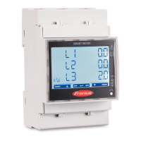
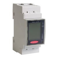
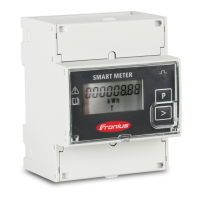
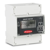
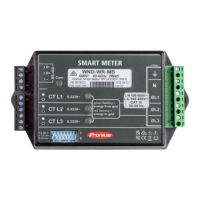
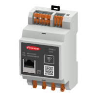
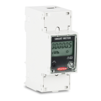
Introduces the Fronius Smart Meter TS and its primary function in optimizing self-consumption.
Describes the device, its markings, safety symbols, and compliance marks.
Defines the product's intended application and lists package contents.
Provides guidance on where to install the Fronius Smart Meter TS within the system.
A step-by-step checklist for correctly installing the Fronius Smart Meter TS.
Covers mounting the device on a DIN rail and the required protective circuit installation.
Details recommended wiring, torque, and connection diagrams for mains and data cables.
Explains fitting terminal covers and connecting the data communication cable to the inverter.
Explains the purpose, symbols, and connection of terminating resistors for Modbus communication.
Illustrates different options for connecting terminating resistors to prevent interference.
Provides instructions on how to mount the connection cover.
Explains symbols used in multi-meter systems and lists Modbus participants.
Details Modbus participants and multi-meter system setup for SnapInverter and GEN24.
Describes the menu structure and lists various measured variables displayed on the device.
Details the configuration menu structure and parameters for the device.
Provides step-by-step instructions on how to set the Modbus address for the meter.
Guides on connecting to Fronius Datamanager and configuring the meter for SnapINverter systems.
Details the steps to configure the Fronius Smart Meter TS as a secondary meter with SnapINverter.
Covers installation and configuration for GEN24 inverters using web browser access.
Explains how to configure the meter as primary or secondary for GEN24 inverters.
Lists specifications for measuring input, data output, and RS485 communication.
Details insulation, EMC, operating conditions, housing, and terminal specifications.
Provides information on the manufacturer's warranty and registration procedures.
| Brand | Fronius |
|---|---|
| Model | TS 65A-3 |
| Category | Measuring Instruments |
| Language | English |
