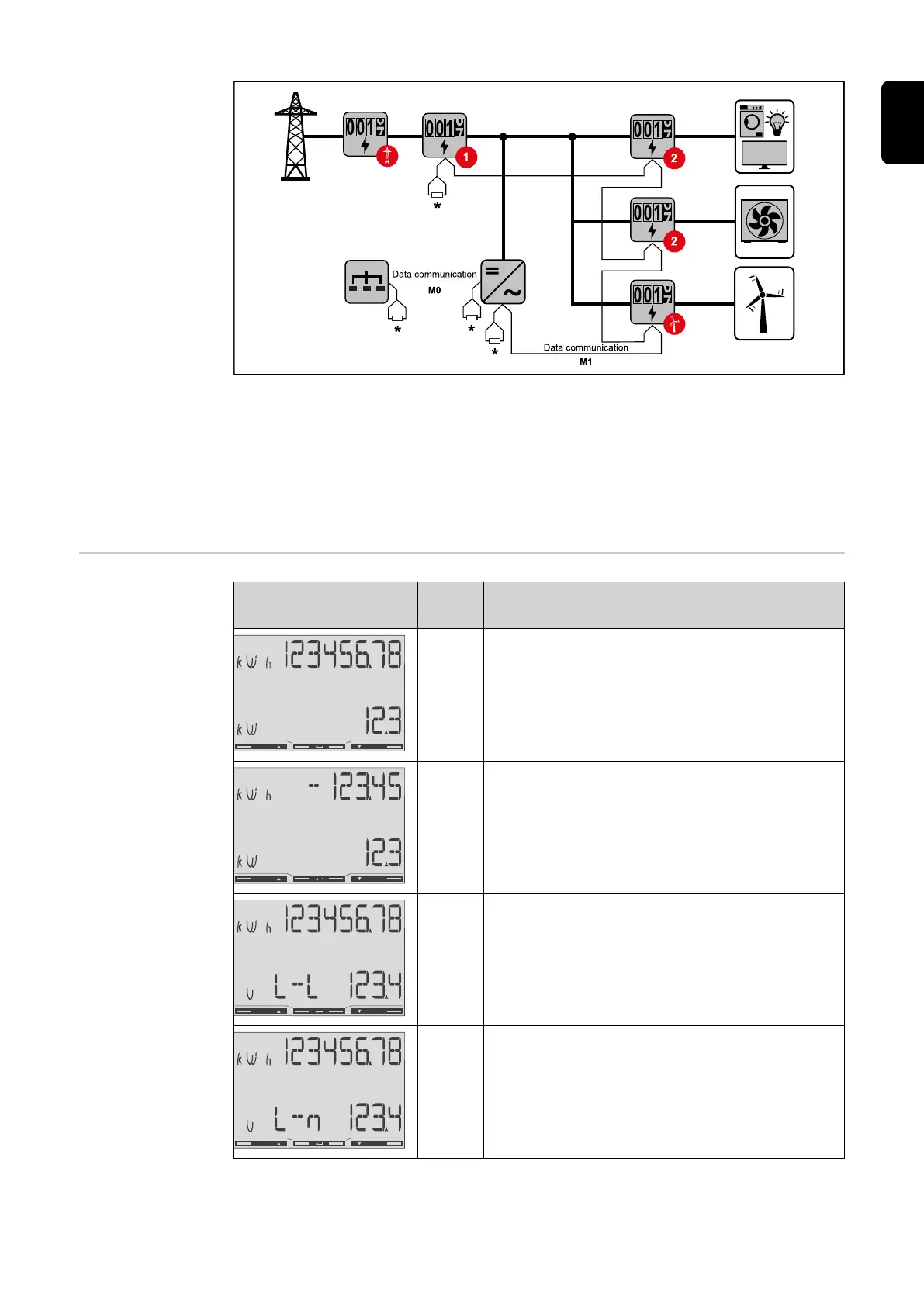
Location of the primary meter at the feed-in point. *Terminating resistor R 120 Ohm
The following must be observed in a multi-meter system:
-
Connect the primary meter and the battery to different channels (recom-
mended).
-
The remaining Modbus participants must be distributed equally.
-
Only assign each Modbus address once.
-
Terminating resistors must be positioned individually for each channel.
Menu - Measured
variables
Image Scree
n
Description
00
1.
Total active energy drawn*
2.
Total efficiency
01
1.
Total active energy supplied**
2.
Total efficiency
02
1.
Total active energy drawn*
2.
Average conductor voltage in the system
03
1.
Total active energy drawn*
2.
Average phase voltage in the system
27
EN