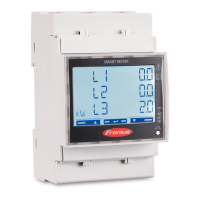
The Fronius Smart Meter 63A-1 is a bidirectional electricity meter designed to optimize self-consumption and record household load curves, particularly in conjunction with Fronius inverters, Datamanagers, and data interfaces. It provides a clear overview of a user's own power consumption by measuring power flow to loads or the grid and transmitting this information via Modbus RTU/RS485 communication to the Fronius inverter.
Function Description:
The Smart Meter acts as a central component in energy management systems, enabling dynamic feed-in control and detailed energy profiling. It can be configured as a primary meter, secondary meter, or producer meter, each serving distinct functions:
- Primary Meter: Records the system's overall load curve and provides measurement data for energy profiling in Fronius Solar.web. Crucially, it also controls dynamic feed-in.
- Secondary Meter: Records the load curve of individual loads (e.g., washing machines, lamps, heat pumps) within the consumption branch, providing data for energy profiling in Fronius Solar.web.
- Producer Meter: Records the load curve of individual producers (e.g., wind power plants) in the consumption branch, supplying measurement data for energy profiling in Fronius Solar.web.
The device supports multi-meter systems, allowing for the connection of multiple Smart Meters and other Modbus participants like Fronius Ohmpilot or Fronius Solar Battery. In such setups, each Smart Meter requires a unique address, with the primary meter always assigned address 1. The system supports up to 4 Modbus participants for SnapINverter systems and up to 4 Modbus participants (across M0 and M1 inputs) for GEN24 inverters. For SnapINverter, only one primary meter, one battery, and one Ohmpilot can be connected per inverter, with the battery occupying two participant slots due to high data transfer. For GEN24, the system can accommodate up to 7 secondary meters.
Important Technical Specifications:
- Nominal voltage (1-phase): 230 V
- Operating range: ±10%
- Self-consumption - voltage path (max. voltage): 4 VA (1.9 W) for 264 V
- Nominal frequency: 50 - 60 Hz
- Tolerance: 47 to 61 Hz
- Nominal current, Ib: 10 A
- Maximum current, Imax: 63 A
- Starting current: 40 mA
- Short-time overload (EN/IEC 62053-21, EN/IEC 62053-23): 30 Imax / 0.5 s
- Self-consumption - current path (max. current): 1.5 W
- Power factor operating range (EN/IEC 62053-21, EN/IEC 62053-23): cosφ 0.5 ind to 0.8 cap
- Current distortion factor: In accordance with EN 62053-21
Output:
- Pulse output: Optical relay with NO contact SPST-NO, floating
- Contact load: 110 V DC/AC - 50 mA
- Pulse value (programmable): 1 imp/Wh - 10 Wh - 100 Wh - 1 kWh
- Pulse duration (programmable): 50 - 100 - 150 - 200 - 300 - 400 - 500 ms
RS485 Communication:
- Electrically isolated from measuring input
- Standard: RS485 - 3 conductors
- Transmission: Serial, asynchronous
- Protocol: Compatible with Modbus RTU
- Addresses: 1 to 255
- Number of bits: 8
- Stop bit: 1
- Parity bit: None - odd - even
- Baud rate: 2400 - 4800 - 9600 - 19200 bit/s
- Response time: ≤ 200 ms
- Modbus transmission speed: 9600 baud
- Parity bit: None
- Software version: Datamanager 3.7.2 / Energypackage 1.3.3
Insulation (EN/IEC 62052-11, 62053-21):
- Installation category: III
- Pollution level: 2
- Insulation voltage: 300 V
Electromagnetic compatibility:
- Emission test: In accordance with EN/IEC 62052-11, EN 50470
- Immunity test: In accordance with EN/IEC 62052-11, EN 50470
Operating conditions:
- Reference temperature: 23°C (±2°C)
- Operating range: -25 to 55°C
- Temperature limit for storage and transport: -40 to 70°C
- Tropical model: Yes
- Max. power loss (for thermal dimensioning of the switch cabinet): ≤ 4 W
- Mechanical environment: M1
- Electromechanical environment: E2
Housing:
- Housing: 2 modules according to DIN 43880
- Sealable front and terminal cover: Yes
- Connection: Screw connection
- Mounting: Can be snapped onto 35 mm DIN rail
- Housing material: Polycarbonate, self-extinguishing
- Degree of protection (EN 60529): IP51 front, IP20 connections
- Weight: 250 grams
Screw terminals:
- Measuring input (Wire rigid): Min. 1 mm² / max. 16 mm²
- Measuring input (Wire flexible): Min. 1 mm² / max. 10 mm²
- Measuring input (Recommended torque): 1.2 Nm / max. 1.4 Nm
- Output (Wire rigid): Min. 0.05 mm² / max. 4 mm²
- Output (Wire flexible): Min. 0.05 mm² / max. 2.5 mm²
- Output (Recommended torque): 0.5 Nm / max. 0.8 Nm
Usage Features:
- Installation Flexibility: The Fronius Smart Meter can be installed at two possible locations: the feed-in point (where power enters the grid) or the consumption point (where power is consumed by loads). It mounts on a 35 mm DIN rail and has a housing comprising 2 modules according to DIN 43880.
- Safety: The device is hard-wired and requires a disconnecting device (circuit breaker, switch, or disconnector) and overcurrent protection (automatic circuit breaker). Automatic circuit breakers should be rated for a maximum of 63 A. All cables must be secured, undamaged, insulated, and adequately dimensioned.
- Cabling: For current path connections, rigid wires from 1 mm² to 16 mm² or flexible wires from 1 mm² to 10 mm² are recommended, with a torque of 1.2 Nm to 1.4 Nm. For data communication and neutral conductor connections, rigid wires from 0.05 mm² to 4 mm² or flexible wires from 0.05 mm² to 2.5 mm² are recommended, with a torque of 0.5 Nm to 0.8 Nm. Only one cable per screw terminal should be installed.
- Data Communication: Connects to Fronius inverters via Modbus RTU/RS485. For SnapINverter, connections are made to the inverter's system monitoring. For GEN24 inverters, connections are made to the Modbus interface. CAT5 or higher cables are recommended for data communication, with mutual twisted pairs for data lines (D+, D- and M1+, M1-). Shielded twisted pair cables are advised to avoid faults.
- Terminating Resistors: To ensure proper functioning and avoid interference in Modbus systems, terminating resistors (R 120 Ohm, included) are recommended. These should be positioned as illustrated in the manual, typically at the ends of the Modbus line.
- Commissioning: Involves switching off power, mounting the meter, connecting protective circuits and mains cables, connecting data communication to the inverter, setting terminating resistors, and verifying secure connections. Firmware updates for the inverter are crucial for compatibility.
- Address Setting: If multiple Smart Meters are installed, each must have a unique address (1-14). The primary meter is always address 1. This is set via the device's menu structure using the "Prog" button and a password.
- Configuration via Datamanager (SnapINverter): Access the inverter's Wi-Fi Access Point or LAN, navigate to the Fronius Datamanager website, log in as "service," and configure the meter type (primary or secondary) and its position (feed-in or consumption point).
- Configuration via Web Browser (GEN24 Inverter): Access the inverter's Wi-Fi Access Point or LAN, open the installation wizard via the IP address, and configure system components in Solar.web. For meter configuration, log in as "Technician," access the "Components" menu, add the component, set its position, Modbus address, name, and category (producer or load).
Maintenance Features:
- Safety Notices: All safety and danger notices on the device must be kept legible, undamaged, and uncovered.
- Qualified Personnel: All commissioning, maintenance, and servicing must be carried out by suitably qualified personnel with knowledge of electrical installations.
- Original Spare Parts: Only original spare parts should be used for repairs.
- No Modifications: Alterations, installations, or modifications to the device should not be carried out without manufacturer permission.
- Component Condition: Components that are not in perfect condition must be changed immediately.
- Protection Devices: The device should only be operated when all protection devices are fully functional. Faulty safety devices must be repaired by an authorized specialist before operation. Protection devices should never be bypassed or disabled.
- Warranty: Detailed, country-specific warranty terms are available on the Fronius website (www.fronius.com/solar/warranty). Registration on www.solarweb.com is required to obtain the full warranty period for newly installed Fronius inverters or storage systems.