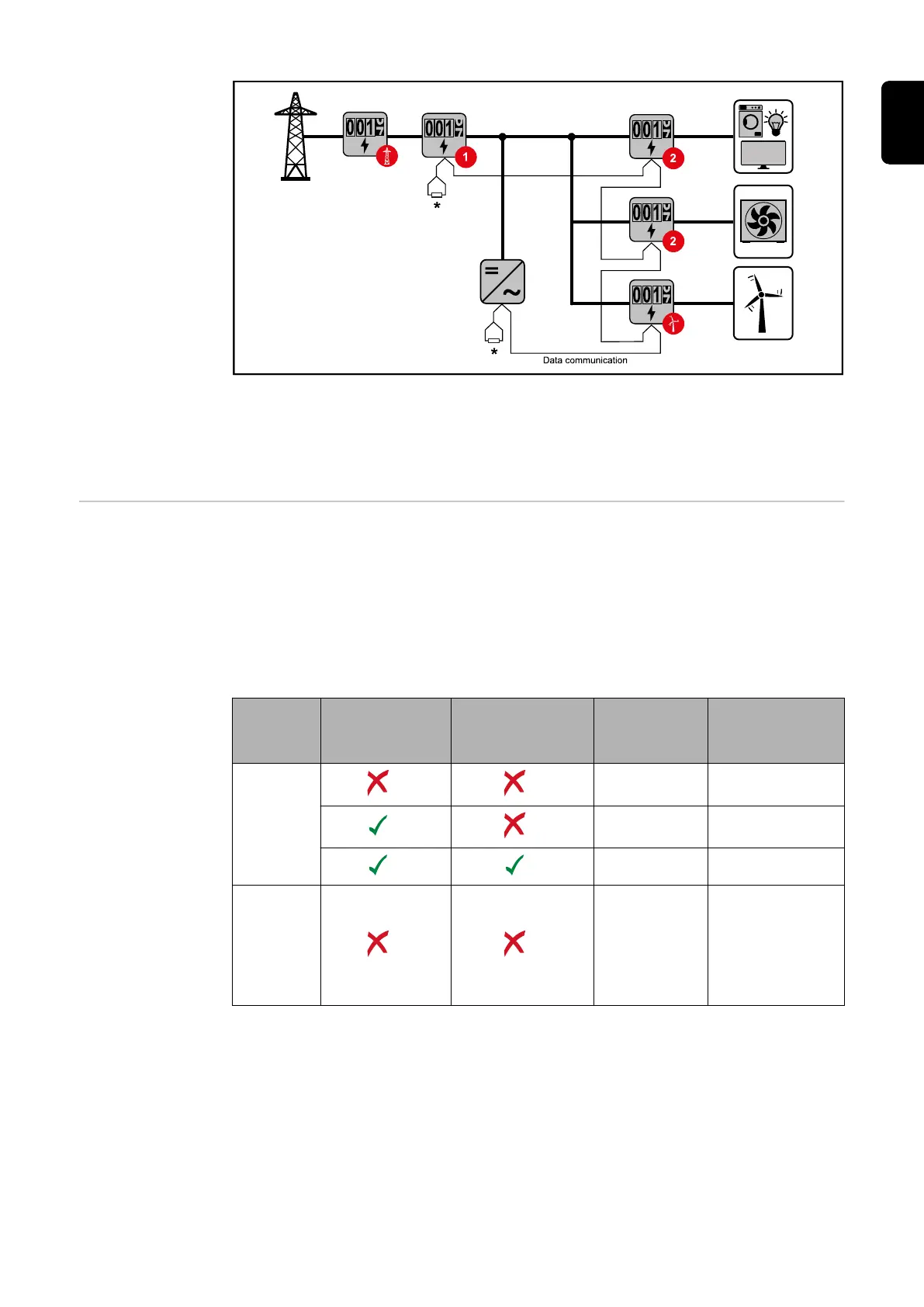
Location of the primary meter at the feed-in point. *Terminating resistor R 120 Ohm
The following must be observed in a multi-meter system:
- Only assign each Modbus address once.
- Terminating resistors must be positioned individually for each channel.
Modbus parti-
cipants - Fronius
GEN24
The inputs M0 and M1 can be selected for this purpose. A maximum of 4 Modbus parti-
cipants can be connected to the Modbus terminal on inputs M0 and M1.
IMPORTANT!
Only one primary meter, one battery and one Ohmpilot can be connected per inverter.
Due to the high data transfer of the battery, the battery occupies 2 participants.
Example 1:
Input Battery
Fronius
Ohmpilot
Quantity
Primary
meter
Quantity
Secondary
meter
Modbus 0 (M0)
0 4
0 2
0 1
Modbus 1 (M1)
1 3
15
EN