Cabling
WARNING!
Danger from mains voltage.
An electric shock can be fatal.
▶
Switch off the power supply before connecting the mains voltage inputs to the
Fronius Smart Meter.
IMPORTANT!
Do not install more than one cable per screw terminal. If necessary, use terminal blocks.
Current path connection cross-section:
- Wire (rigid): min. 1 mm² / max. 16 mm²
- Wire (flexible): min. 1 mm² / max. 10 mm²
- Recommended torque: 1.2 Nm / max. 1.4 Nm
Data communication and neutral conductor connection cross-section:
- Wire (rigid): min. 0.05 mm² / max. 4 mm²
- Wire (flexible): min. 0.05 mm² / max. 2.5 mm²
- Recommended torque: 0.5 Nm / max. 0.8 Nm
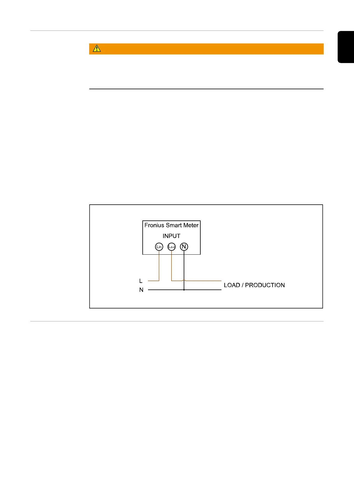
Connect each voltage cable to the terminal strip as shown in the graphic below.
Connecting the
data communica-
tion cable to the
inverter
Fronius SnapINverter:
Connect the data communication connections of the Fronius Smart Meter to the Fronius
system monitoring in the inverter. Several Smart Meters can be installed in the system,
see chapter Multi-meter system - Fronius SnapINverter on page 14.
9
EN