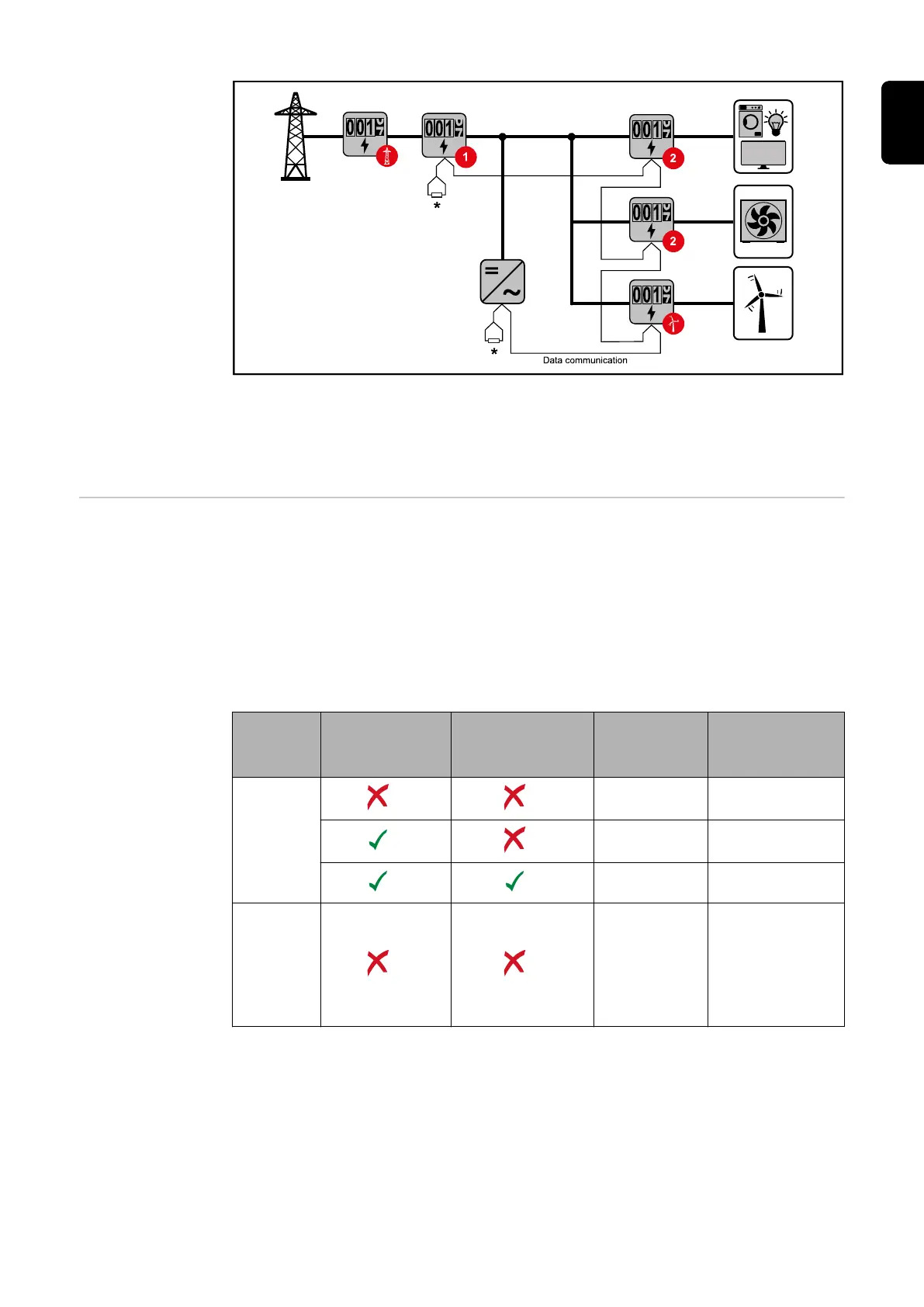
Location of the primary meter at the feed-in point. *Terminating resistor R 120 Ohm
The following must be observed in a multi-meter system:
-
Only assign each Modbus address once.
-
Terminating resistors must be positioned individually for each channel.
Modbus parti-
cipants - Fronius
GEN24
The inputs M0 and M1 can be selected for this purpose. A maximum of 4 Modbus
participants can be connected to the Modbus terminal on inputs M0 and M1.
IMPORTANT!
Only one primary meter, one battery and one Ohmpilot can be connected per in-
verter. Due to the high data transfer of the battery, the battery occupies 2 parti-
cipants.
Example 1:
Input Battery
Fronius
Ohmpilot
Quantity
Primary
meter
Quantity
Secondary
meter
Modbus 0 (M0)
0 4
0 2
0 1
Modbus 1 (M1)
1 3
25
EN