Example 2:
Input Battery
Fronius
Ohmpilot
Quantity
Primary
meter
Quantity
Secondary
meter
Modbus 0 (M0)
1 3
Modbus 1 (M1)
0 4
0 2
0 1
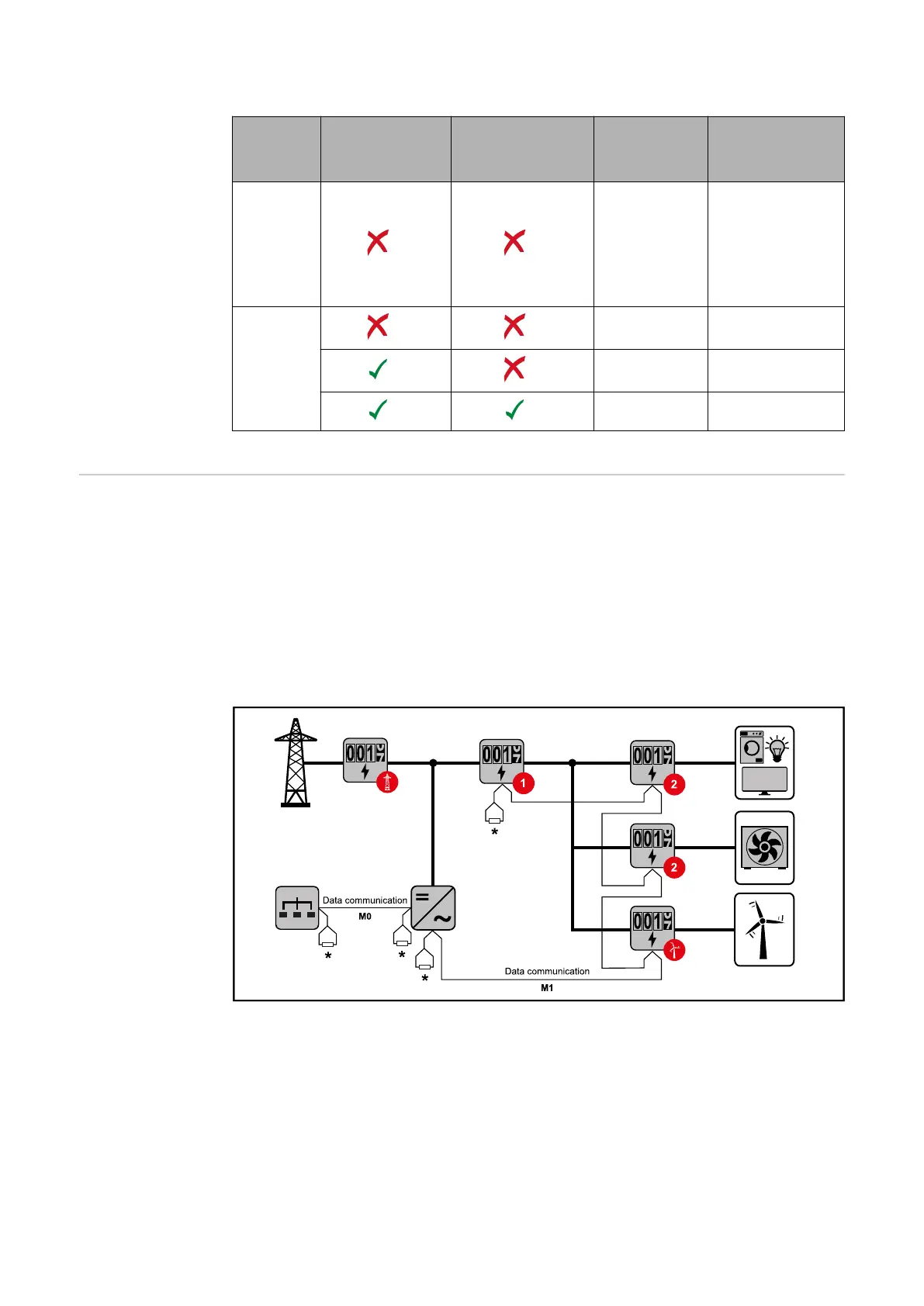
Multi-meter sys-
tem - Fronius
GEN24 inverter
If several Fronius Smart Meter TS are installed, a separate address must be set
for each (see Setting the address on the Fronius Smart Meter TS on page 31).
The primary meter is always assigned address 1. All the other meters are
numbered consecutively with the address range from 2 to 14. Different Fronius
Smart Meter power categories can be used in combination.
IMPORTANT!
Max. Use 7 secondary meters in the system. To avoid interference, it is recom-
mended to install the terminating resistors according to chapter Connecting the
terminating resistor on page 21.
Location of the primary meter in the consumption branch. *Terminating resistor R 120 Ohm
26