Installation
Checklist for in-
stallation
For installation information, see the following chapters:
1
Switch off the power supply before establishing a mains connection.
2
Mount the Fronius Smart Meter TS (see "Installation" on page 17).
3
Connect automatic circuit breakers or automatic circuit breakers and discon-
nectors (see"Protective circuit" on page 17).
4
Connect the mains cable to the Fronius Smart Meter TS (see "Cabling" on
page 18).
5
Fit the protective cover for the terminals (see "Fitting the protective cover
for the terminals" on page 19).
6
Connect the data communication connections of the Fronius Smart Meter
TS to the Fronius system monitoring using a suitable cable (see "Connecting
the data communication cable to the inverter" on page 19).
7
If necessary, set terminating resistors (see "Connecting the terminating res-
istor" on page 21).
8
Tug on each wire and plug to make sure that they are securely connected to
the terminal blocks.
9
Switch on the power supply to the Fronius Smart Meter TS.
10
Check the firmware version of the Fronius system monitoring. To ensure
compatibility between the inverter and the Fronius Smart Meter TS, the soft-
ware must always be kept up to date. The update can be started via the in-
verter web page or using Solar.web.
11
If several Fronius Smart Meter TS are installed in the system, set the address
(see "Setting the address" under "Setting the address on the Fronius Smart
Meter TS" on page 31).
12
Configure and commission the meter (see Start-up on page 33).
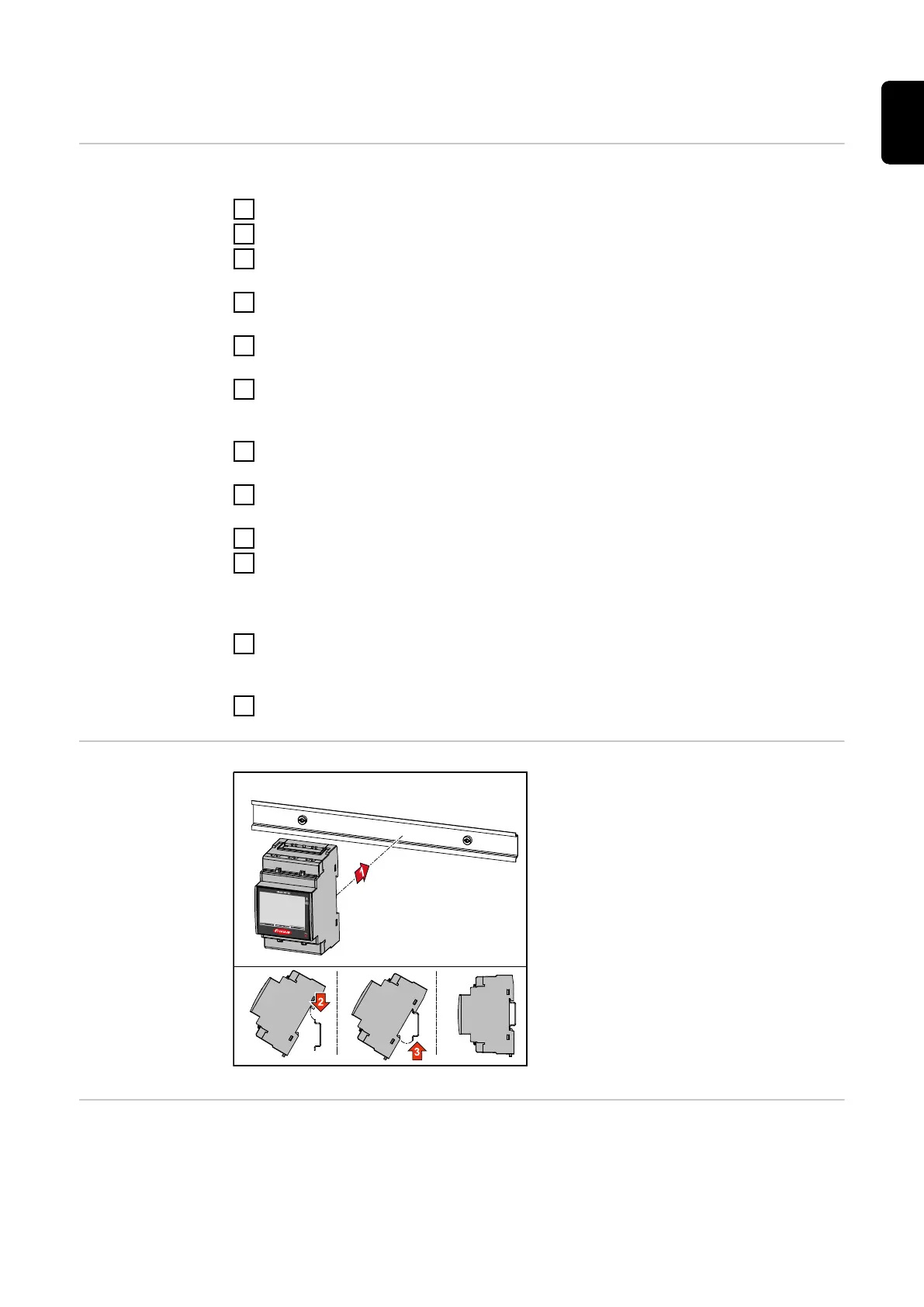
Installation The Fronius Smart Meter TS can be
mounted on a 35 mm DIN rail. The
housing comprises 3 modules accord-
ing to DIN 43880.
Protective cir-
cuit
The Fronius Smart Meter TS is a hard-wired device and requires a disconnecting
device (circuit breaker, switch or disconnector) and overcurrent‑protection (auto-
matic‑circuit breaker).
17
EN