4
MAINS ON/OFF SWITCH (see Fig.9)
DIGITAL-AMMETER
- Indicator of the main current
Command value ð desired welding current
Actual value ð actual welding current
DIGITAL-VOLTMETER
- Indicator of the welding voltage
FUNCTION BUTTON
a) 2-step operation
b) 4-step operation
c) 2-step operation +
d) 4-step operation +
- Arc force control and hot-start devices are out of action
- When the TR 50mc, TR 51mc and TR 52mc remote-control
units are used, the system switches over to the operating
mode in question automatically
- LED indicators
or resp. + or + lights up
e) MANUAL ELECTRODE WELDING
- LED indicator lights up and the digital voltmeter indicates
the open-circuit voltage.
- The welding characteristics are governed by the values for
ARC FORCE and HOT-START which are fixed in the machi-
ne itself.
- It is possible to influence these parameters from outside via
the TPmc remote control unit and the inert menue at function
selector switch position
LED INDICATOR for manual electrode welding
- Select via function button
- LED indicator lights up (for main current I
H
) only at welding
- Welding current is present in the current sockets ,
- Welding current is either adjusted with the main current re-
gulator , or via the dial on the TPmc remote control unit
LED INDICATOR for contact ignition
- Select via function button
- Lights up together with either LED or LED
- To ignite the arc, touch the workpiece with the tungsten
electrode after pressing the torch trigger.
- The short-circuit current flowing when contact is made bet-
ween the electrode and the workpiece corresponds to the
minimum current.
Where to use contact ignition: Whenever the HF used in
contact-free ignition would cause external interference.
LED INDICATOR FOR 4-STEP MODE
4-step mode
4-step mode - without intermediate lowering
- In the manual or automatic welding modes, for flawless
welding joints
- Pre-settable parameters such as gas pre-flow, start arc,
upslope time, main current, downslope time, crater-fill cur-
rent and gas post-flow time
- In the "PRESETTINGS LEVEL ---" program-level (see "Wor-
king with the program-levels"), parameter TIG, the setting
for SFS must be set to "OFF"
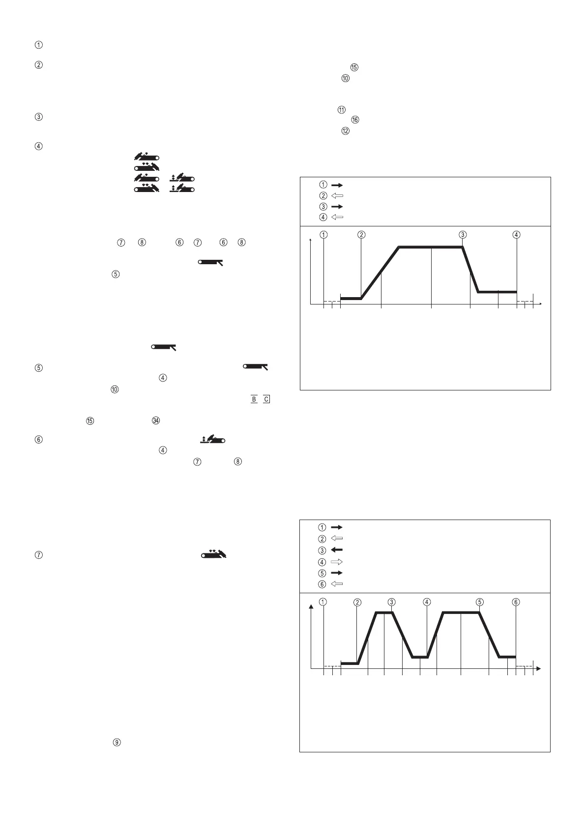
Functional sequence (Fig.4):
1. Pull back and hold the torch trigger
- Gas pre-flow time elapses
- Arc ignites at the pre-set value for start-arc current I
S
(with
HF ignition: HF cuts out automatically after ignition)
- LED indicator lights up
}
}
TIG-welding with
HF-ignition
TIG-welding with
contact ignition
2. Release trigger
- Welding current rises via the pre-set upslope to the value set
on dial
for the welding current I
H
- LED lights up
3. Pull back and hold the torch trigger once again
- Welding current drops during the pre-set time (downslope,
dial ) until it reaches the value set for the crater-fill current
I
E
(dial , crater-filling)
- LED
lights up
4. Release the torch trigger
- Arc goes out
- The internally pre-set gas post-flow time elapses
4-step mode - with intermediate lowering (Fig.4a)
- Activated from TIG torch with double-pushbutton function
- Intermediate lowering down to reduced current I
E
:
- Facility for lowering the welding current from the main
current to the reduced current I
E
and back, without
interrupting the welding sequence
- In the "PRESETTINGS LEVEL ---" program-level (see "Wor-
king with the program-levels"), parameter TIG, the setting
for SFS must be set to "OFF"
Start of cycle
Gas pre-flow time
Current rises via
upslope
Current drops via
downslope
Gas post-flow time
End of welding
Crater-fill
current
Pull back and hold the torch trigger
Release the torch trigger
Release the torch trigger
Arc ignites with start-arc
current I
S
Welding with pre-set
main current I
H
Fig. 4 Functional sequence in 4-step mode - without intermediate lowering
Pull back and hold the torch trigger
I
S
I
H
I
E
I
t
Push forward and hold the torch trigger
Release the torch trigger
Release the torch trigger
Fig. 4a Functional sequence in 4-step mode - Variant I - with intermediate
lowering
Pull back and hold the torch trigger once again
I
S
I
H
I
E
I
t
Pull back and hold the torch trigger
Release the torch trigger
I
E
I
H
Start of cycle
Gas pre-flow time
Current rises via
upslope
Current drops via
downslope
Gas post-flow time
End of welding
Crater-fill
current
Arc ignites with start-arc
current I
S
Welding with pre-set
main current I
H
Current rises via
upslope
Current drops via
downslope
Welding with pre-set
main current I
H
Crater-fill
current
 Loading...