8
OVERTEMPERATURE INDICATOR lights up
- If the unit is overloaded
- If the temperature has been reached on the primary heat
sink, on the secondary heat sink (see Fig.1)
MARK LED INDICATOR
- lights up when the monitoring function is activated
- this LED indicates that the AC voltage in the welding current
circuit does not exceed 48 V
TIG TORCH CONNECTION
- for connecting the GAS + CURRENT supply for the welding
torch at gas cooled units
- for connecting the WATER + CURRENT supply for the
welding torch at water cooled units
SOCKET with bayonet coupling
- as the earth cable connection point with TIG welding;
- as the connection either for the manual electrode cable or
the earth cable with manual electrode welding, depending
on the type of electrode used.
SOCKET with bayonet coupling
- as the connection either for the manual electrode cable or
the earth cable with manual electrode welding, depending
on the type of electrode used.
The following parameters are laid down
- Gas pre-flow time ....................................... 0,4 sec.
- Start arc: 36 % of I
H
in DC mode ............... 36% of I
H
50 % of I
H
in AC mode ................................ 50% of I
H
- Up-slope ..................................................... 1,0 sec.
- Gas post-flow time ...................................... 5-15 sec.
- Frequency .................................................. 60 Hz
All parameters can be changed individually, via a program menu.
Type of
current
Current load
too low
too high
a) b) c)
AC
~
correct
good for
root passes and
thin workpieces
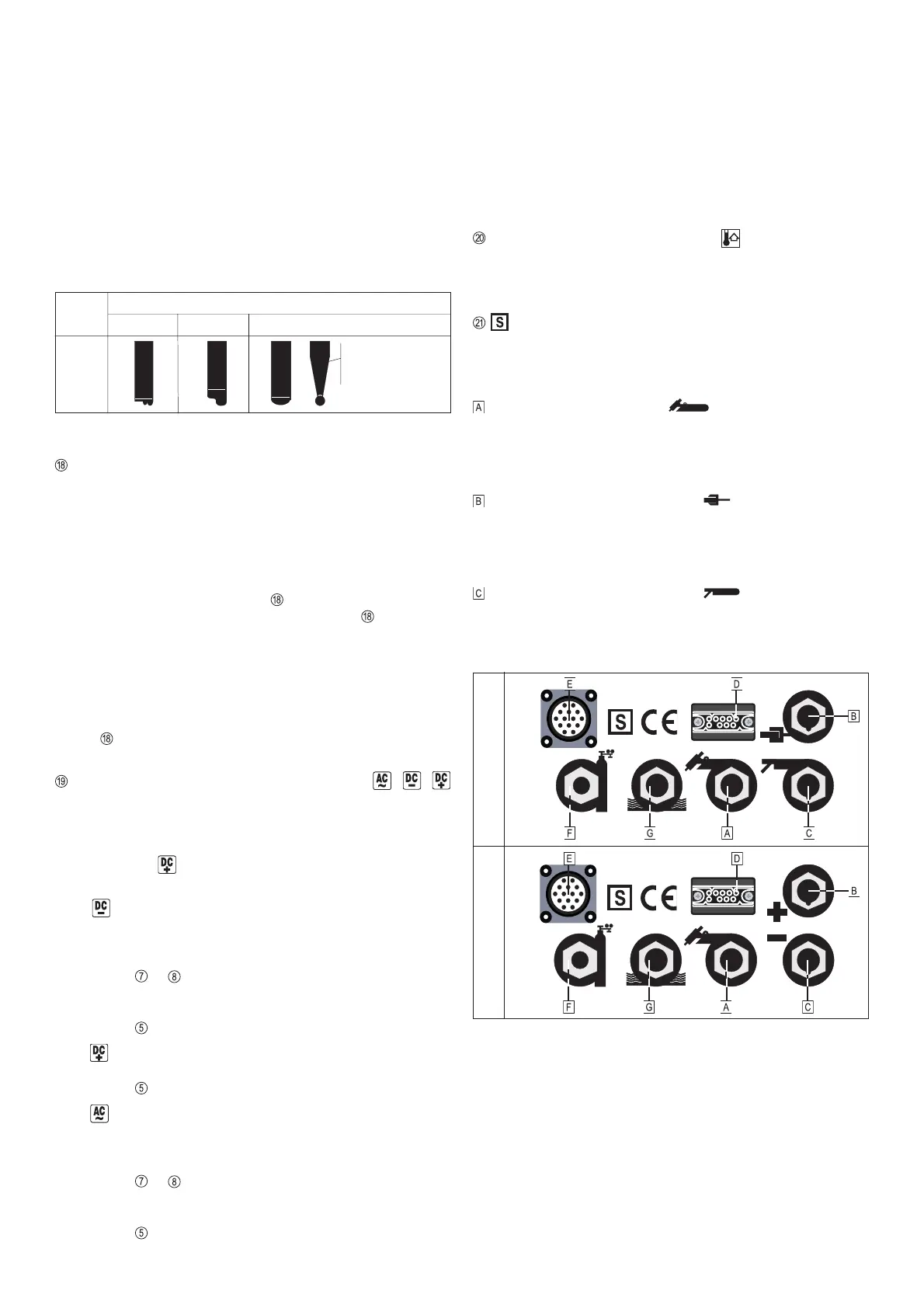
Fig.7 Shapes of formed on tungsten electrodes subjected to different loads in
the AC range
Examples of settings:
a) Balance dial is in position "0"
Neutral setting
b) Balance dial is in position "+5"
The positive half-waves are longer than the negative ones =
long cleaning phase but reduced penetration depth; in-
creased load on tungsten electrode - cap formed on elec-
trode tip is too large (Fig.7b)
c) Balance dial is in position "-5"
The negative half-waves are longer than the positive ones =
long penetration phase but reduced cleaning effect; tungs-
ten electrode is underloaded - no cap formed on electrode
tip (Fig. 7a)
ADJUSTMENT DIAL FOR DIAMETER OF
TUNGSTEN ELECTRODE (von 0 - 4,0mm)
a) AC-operation: (only MW 2600 / 2600 CEL / 3000)
For automatic formation of a spherical tip to the tungsten
electrode. Before starting to weld, briefly push the torch
trigger forward and then initiate the welding operation. A
spherical tip is then formed on the - pointed or blunt - tung-
sten electrode, as determined by the electrode-diameter
value set beforehand on dial .
- If the torch trigger is not pushed forward, dial can be used
to set the ignition current for the diameter of tungsten
electrode in question.
b) DC-operation:
- Is used to set the ignition current for the diameter of tung-
sten electrode in question.
When the machine is in the “Electrode" modes, adjustment
dial is inactive.
SELECTOR BUTTON for TYPE OF CURRENT / /
(only on MW 2600 / 2600 CEL / 3000)
This is used for selecting the type of current required, and for
reversing the polarity with both TIG and ROD ELECTRODE
MANUAL WELDING.
At TIG mode
is locked.
Functional description:
1.
: Direct current ð TIG welding of unalloyed, low and high
alloy steels, Sn or Cu bronzes, copper etc.
a) TIG mode
- Minus pole is on the tungsten electrode
- Led
or lights up
b) MANUAL ELECTRODE mode
- Minus pole is on the rod electrode
- Led
lights up
2. : Direct current ð Manual electrode welding
- The plus pole is on the rod electrode
- Led
lights up
3.
: Alternating current ð TIG welding of aluminium and
its alloys, aluminium-bronze etc.
a) TIG mode
- Alternating current is on the tungsten electrode
- Led
or lights up
b) MANUAL ELECTRODE mode
- Alternating current is on the rod electrode
- Led
lights up
Fig.8 Design with central welding torch connection GWZ: Connection points on
front of machine
TRANSTIG MAGIC WAVE
 Loading...