7
Special 2-step mode (Fig.6a)
- is activated from TIG torch trigger
- is mainly used for tack welding
- In the "PRESETTINGS LEVEL ---" program-level (see "Wor-
king with the program-levels"), parameter TIG, the setting
for StS must be set to "ON"
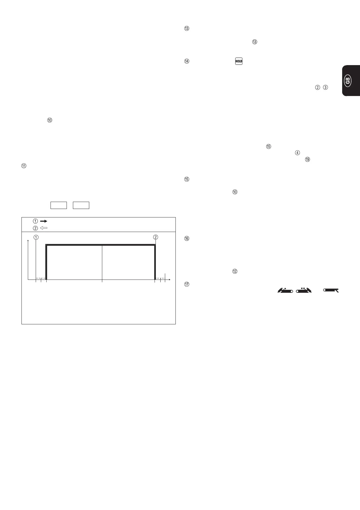
Functional sequence:
1. Pull back and hold the torch trigger
- Gas pre-flow time elapses
- Arc ignites at the pre-set value for start-arc current I
S
(with
HF ignition: HF cuts out automatically after ignition)
- Welding current rises, without upslope, to the welding-
current value I
H
- LED lights up
2. Release the torch trigger
- Arc goes out (without the current being lowered)
- The internally pre-set gas post-flow time elapses
When the remote-control pedal unit TR 52mc is used, the
machine automatically switches over to 2-step mode.
DOWNSLOPE or current drop time:
- Continuously adjustable current-lowering rate from main
current to crater-fill current I
E
Adjusting range: from 0.1 to 20 seconds
- When the downslope potentiometer is actuated, the pre-set
value is indicated for 3 seconds
e.g.: d S L 1.0
Start of cycle
Gas pre-flow time
End of welding
Gas post-flow time
Pull back and hold the torch trigger
Release the torch trigger
Arc ignition
Welding with pre-set
main current I
H
Fig. 6a Functional sequence in special2-step mode
I
H
I
t
LED INDICATOR FOR TIG PULSED-ARC WELDING
- As soon as the TR 50mc TIG remote-control pulsing unit is
connected up, the LED
(see "TR 50mc TIG remote-control
pulsing unit") starts to flash
LED INDICATOR
- enables retrospective verification of the welding parameters
- lights up after actual values have been stored (end of
process)
- average value is indicated on the digital displays , (the
values measured for welding current and voltage before the
end of a welding operation)
- function is not available when a remote-control pedal unit is
being used, or when the arc is pulsed at 20Hz or below
Possible ways of clearing the HOLD function
- Actuate the torch trigger during the weld-off period
- Switch the machine off and then back on again
- Adjust the main-current dial during the weld-off period
- Switch over the function selector button
- Switch over the current-type selector button
- Every time a new welding operation is started
MAIN-CURRENT DIAL I
H
= welding current
- Continuous adjustment throughout a 3-260/300 A range
- LED indicator lights up (only in "Electrode" mode)
- Digital ammeter indicates the command value for the cur-
rent, already in open circuit, and then switches over to
displaying the actual value
Command value ð desired welding current
Actual value ð actual welding current
CRATER-FILL CURRENT I
E
- Only possible in 4-step mode
- Set as a percentage of the main current
- Operator lowers the welding current down to the crater-fill
current by pressing the torch trigger
- LED indicator lights up
BALANCE DIAL (only MW 2600 / 2600 CEL / 3000)
- Only functions in the AC range in , and
modes
- Positive and negative half-waves can be changed
- For better adaptation to the welding problem in question
(optimisation of cleaning and penetration behaviour)
- For optimised electrode cap-shaping (Fig.7c)
 Loading...