6
Push forward and hold the torch trigger
Release the torch trigger
Fig. 5c Functional sequence in special 4-step mode - Variant IV
Pull back and release the torch trigger
I
S
I
H
I
E
I
t
Pull back and hold the torch trigger
Release the torch trigger
I
H
Start of cycle
Gas pre-flow time
Current rises via
upslope
Current drops via
downslope
Gas post-flow time
End of welding
Crater-fill current
Arc ignites with start-arc
current I
S
Welding with pre-set
main current I
H
Current rises via
upslope
Welding with pre-set
main current I
H
Start of cycle
Gas pre-flow time
Current rises via upslope
Current drops via
downslope
Gas post-flow time
End of welding
Crater-fill
current
Pull back and hold the torch trigger
Release the torch trigger
Release the torch trigger
Arc ignites with start-arc
current I
S
Welding with pre-set
main current I
H
Fig. 5d Functional sequence in special 4-step mode - Variant V
Push forward and hold the torch trigger
I
S
I
H
I
E
I
t
Current-rise when torch
trigger is pushed forward
Current-drop when torch
trigger is pushed forward
Welding with decreased
main current I
H
Push forward and hold the torch trigger
Release the torch trigger
Pull back and hold the torch trigger
Release the torch trigger
Welding with increased
main current I
H
Variant V (Fig. 5d) allows the welder to raise and lower the welding
current without an Up/Down torch.
The longer the torch-trigger rocker switch is pushed forward
during welding, the more the welding current is increased (up to
maximum).
After the welder releases the torch trigger, the welding current
remains constant. The longer the torch trigger is pushed forward
once again, the further the welding current is reduced.
Diagram showing intermediate lowering
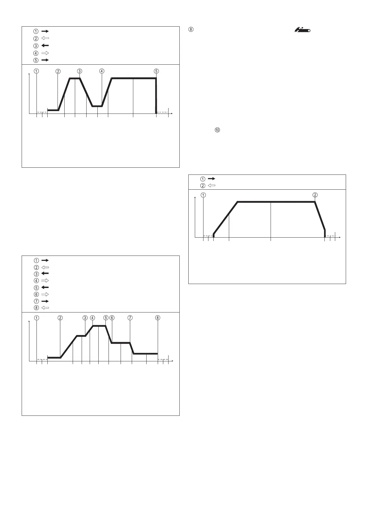
LED INDICATOR FOR 2-STEP MODE
2-step mode (Fig.6)
- is activated from TIG torch trigger
- is mainly used for tack welding
- In the "PRESETTINGS LEVEL ---" program-level, parame-
ter TIG, the setting for StS must be set to "OFF"
Functional sequence:
1. Pull back and hold the torch trigger
- Gas pre-flow time elapses
- Arc ignites at the pre-set value for start-arc current I
S
(with HF
ignition: HF cuts out automatically after ignition)
- After ignition, the welding current rises via the internally pre-
set upslope to the welding-current value I
H
- LED lights up
2. Release the torch trigger
- Arc goes out (with or without the current being lowered)
- Internally pre-set gas post-flow time elapses
When the remote-control pedal unit TR 52mc is used, the
machine automatically switches over to 2-step mode.
Start of cycle
Gas pre-flow time
Current rises via
upslope
End of welding, via
downslope to
crater-fill current I
E
Gas post-flow time
Pull back and hold the torch trigger
Release the torch trigger
Arc ignites with start-
arc current I
S
Welding with pre-set
main current I
H
Fig. 6 Functional sequence in 2-step mode
I
H
I
t
 Loading...