11
ENGLISH
- Set a value between 5 and 10 m/min with the wirefeed-speed dial
- Shift the operating-mode selector switch to the wire-inching position
- Press and hold the torch trigger
- Welding wire runs into the torch hosepack, with no gas or current
- Release the torch trigger to end the wire-inching procedure
N.B.! The wire spool must not continue to unreel after you release the torch
trigger. Re-adjust the brake if necessary.
- Screw in the contact tube
- Fit the gas nozzle
- Replace the left side panel of the power source or the housing of the
wirefeeder unit
- Shift the mains switch into the "0" position
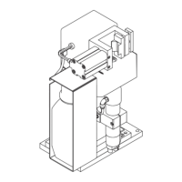
Fig.14 2-roller drive
SETTING THE SHIELDING-GAS RATE
- Open the left side panel of the power source or the housing of the wirefeeder
unit
- Pivot the clamping device
of the motor baseplate forwards
- Pull the pressure lever upwards
- Plug in the machine at the mains
- Shift the mains switch into the “1” position
- Shift the operating-mode selector switch
to the 2-step mode position
- Press and hold the torch trigger
- Turn the adjusting-screw on the underside of the pressure regulator until
the manometer indicates the desired shielding gas flow-rate
- Release the torch trigger
- Shift the mains switch into the “O” position
- Unplug the machine from the mains
- Push the pressure lever downwards
- Latch the clamping device into place
- Replace the left side panel of the power source or the housing of the
wirefeeder unit
CHANGING THE FEED ROLLERS
In order to achieve satisfactory wire travel, the feed rollers must be suitable
for the diameter and alloy of the wire to be welded.
- Shift the mains switch into the “O” position
- Open the left side panel of the power source or the housing of the wirefeeder
unit
- Pivot the clamping device
of the motor baseplate forwards
- Pull the pressure lever upwards
- Pull out the axle
- Remove the pressure roller
- Insert the new pressure roller
- Insert the axle again - the anti-twist lock of the axle must latch into place
- Take out the Allen screw
- Detach the drive roller
- Push on the new drive roller
N.B.! Insert the pressure and drive rollers in such a way that you can still
see and read the designation for the wire diameter.
- Screw in and tighten the Allen screw
- Push the pressure lever downwards
- Pull the clamping device
into the vertical position
- Replace the left side panel of the power source or the housing of the
wirefeeder unit
CORRECTING THE WIRE INFEED
For smooth wirefeed, the wire electrode must run into the torch without
abrading.
Wire infeed in the x and y axes is factory-adjusted to optimum settings.
However, it may be necessary to make corrections in the x axis after
individual components such as wirefeed rollers, the drive motor or the welding
torch have been changed. The wire infeed can then be “fine-tuned” by adding
or taking away spacing discs between the drive roller and the Seeger snap-
ring.
Fig.15 Excessive deviation (not permissible)
X
Spacing discs (10 x 0.1)
N.B.! A height correction (y-axis) can only be carried out by Fronius After-
Sales Service.