High-Effi ciency Gas
2-17
As the probe temperature increases 1°F, the resistance increases by 2 ohms. A probe resistance/
temperature chart is provided in the Charts & Tables section. To check the performance of a
temperature probe, the probe’s reading should be compared to a measurement taken as near as
possible to the probe with an external thermometer or pyrometer.
Probe resistance can be checked from the 15-pin or 20-pin SMT controller plug. The probe
circuits are found by counting pin locations on the plug.
If the probe resistance exceeds the tolerance levels, below 1000 Ω or above 1950 Ω or a short is
detected on either wire, the controls will indicate the problem as follows:
Troubleshooting Probes
Ignition Failure
An alarm signal is sent and the gas valve is
shut off if the module’s microamp sensing cir-
cuit doesn’t confi rm a fl ame in 4 seconds.
When the module locks out, 24VAC is sent
through the interface board alarm circuit to the
controller.
CMIII.5 controls display HELP; M2000 con-
trollers display Ignition Failure; 3000’s display
heat failure.
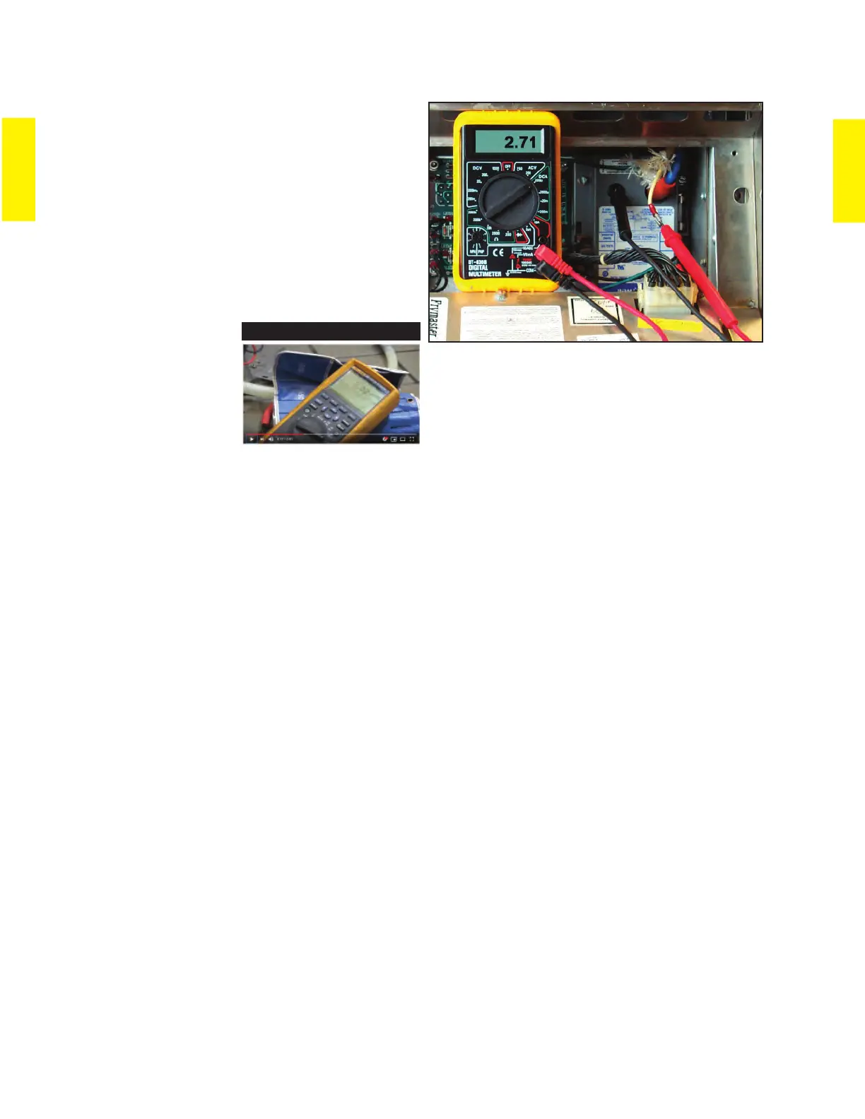
Microamps are measurable by placing a multimeter
capable of measuring microamps (not milliamps)
in series with the white sensing wire on the ignition
module. See output requirements for different igniton
modules on page 2-13.
Video Content
Click to launch YouTube
video on microamp check.
Tips on Troubleshooting Ignition Failure
Take a multi-meter and manometer on every call.
Have the customer describe the specifi c complaint.
Are clues to the problem inherent in the
complaint: happens during lunch hour, etc..
Eliminate components that are obviously working.
Operate the fryer and verify the problem.
Verify a fl ame is in the chamber when the fryer calls for re-ignition.
If no fl ame is present:
Check for power to the gas valve during the restart.
If fl ame is present in the chamber during call for ignition: Check for proper gas pressure
under high-volume conditions (lunch time).
Check microamp level (2.5 - 3.5 microamps for Honeywell module; 0.4 - 0.8 for Capable
Controls; 1.7-3.0 for Fenwal module) for each ignitor’s fl ame sensor.
Determine which side (left or right) is causing the failure. Use the LEDs on the interface to
determine faulty side.
 Loading...