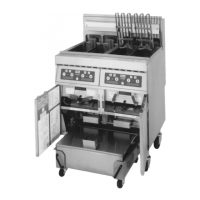
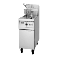
High-Effi ciency Gas
2-20
24-Volt
Transformer
Left Heat
Relay
LED 2 / L-PWR
Left Ignition
Module
V2D
LED 1 / L-GV
High Limit
Safety Drain
Switch
Left Gas Valve
Pin 9 J1
Pin 8 - J3
LED 3 / 24V
Right Heat
Relay
LED 4 / R-PWR
Right Ignition
Module
V1D
LED 5 R-GV
High Limit
Safety Drain
Switch
Right Gas Valve
Pin 9 J3
Air Switch
CE only
Fuse
Dual Vat Single Spark Module
24-Volt
Transformer
Pin 8 - J3
LED 3 / 24V
Right Heat
Relay
LED 4 / R-PWR
Right Ignition
Module
V1S
LED 2 / L-PWR
Left Ignition
Module
V2S
LED 5 / R-GV
Pin 9 J3
High Limit
Safety Drain
Switch
Gas Valve
Fuse
Air Switch
CE only
Full Vat Single Spark Module
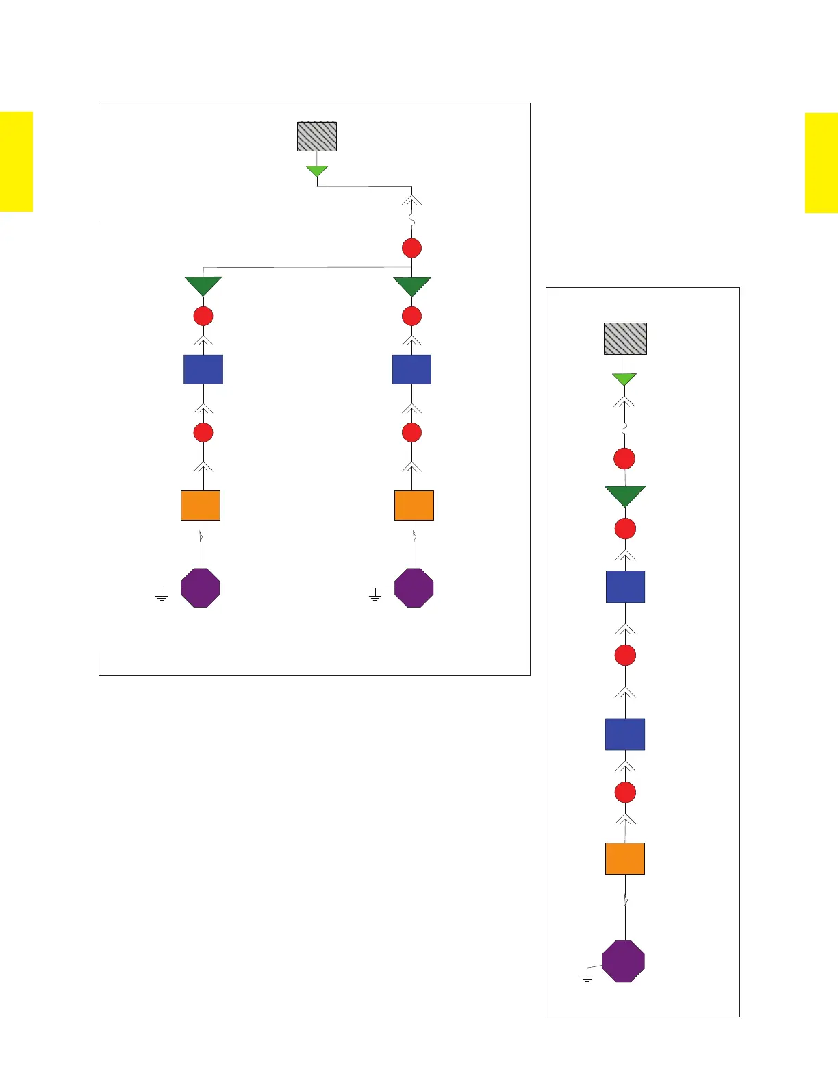
The 24-Volt Circuit
These charts show the
fl ow of electricity through
the circuitry of an HE gas
fryer in normal operation.
All components and wiring
connections are shown.
Full-Vat With Two Single-Spark Modules
Dual-Vat With Two Single-Spark Modules
*
*
*
* On FQ, LOV
position of
7-second OIB
relay.