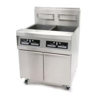
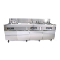
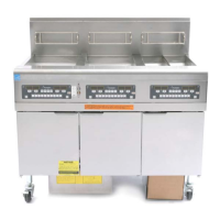
Electric Fryers
3-5
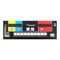
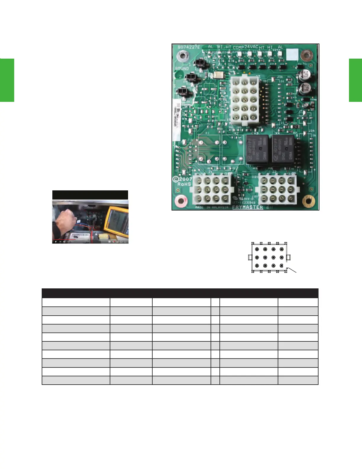
Interface Boards
J1 and J2
RE
(E4)Series
3
2
1
6
5
4
9
8
7
12
11
10
Position 1
RE14/17/22 Test Points
Test Set Meter Pin & Pin Results
12VAC Power 50VAC Scale 3 of J2 & 1 of J2 12-16VAC
24VAC Power 50VAC Scale 2 of J2 & Chassis 24-30VAC
Probe Resistance - RT* R x 1000 Ω 11 of J2 or 13 of J3 & 10 of J2 or 14 of J3
† See chart.
Probe Resistance - LT* R x 1000 Ω 1 of J1 or 15 of J3 & 2 of J1 or 14 of J3
† See chart.
High-limit Continuity - RT R x 1 Ω 9 of J2 & 6 of J2 0- Ω
High-limit Continuity - LT R x 1 Ω 6 of J1 & 9 of J1 0- Ω
Latch Contactor Coil - RT R x 1 Ω 8 of J2 & Chassis 3-10 Ω
Latch Contactor Coil - LT R x 1 Ω 5 of J1 & Chassis 3-10 Ω
Heat Contactor Coil - RT R x 1 Ω 7 of J2 & Chassis 11-15 Ω
Heat Contactor Coil - LT R x 1 Ω 4 of J1 & Chassis 11-15 Ω
* Disconnect the 15-pin harness from the computer or controller before testing the probe circuit.
† See Probe Resistance Chart in Chapter 7 for the correct resistance value.
The electric fryer interface board is similar
to interface boards on the H.E. gas fryers.
LED indicators aid in troubleshooting, and
the board acts as a common junction for
the fryer’s electrical components. Unlike
the gas version, the electric board includes
an additional relay for the latching circuit.
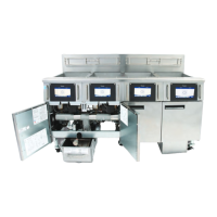
All the wire connections for this circuit are
located on the front side of the board. The
table below provides ten system checks.
The meter reading must agree with the
values in the table.
May 2006 - Current
Video Content
Click to launch YouTube video
on temp probe replacement.
 Loading...