7
EN
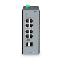
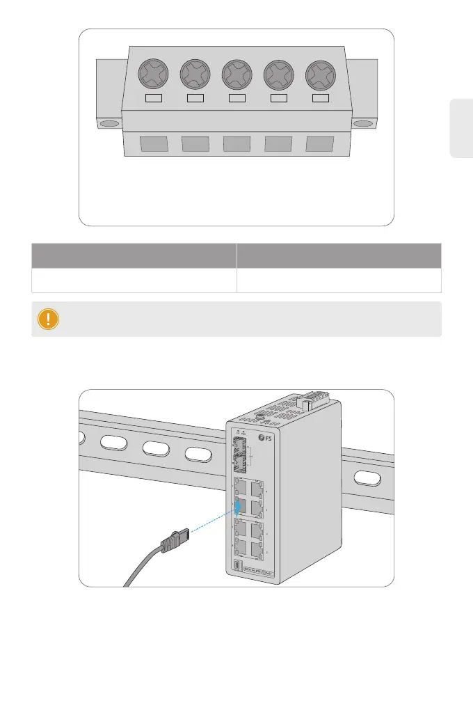
1. Connect an Ethernet cable to the RJ45 port of a camera, outdoor AP, computer or other network
device.
2. Connect the other end of the Ethernet cable to the RJ45 port of the switch.
1
V1+ V1-
PWR1 PWR2
V2- V2+
2 3 4 5
Connecting the RJ45 Ports
NOTE: The wire gauge for the terminal block should be in the range from 12 to 16 AWG.
Pin 2 / 4
Positive (+) Pin Negative (-) Pin
Pin 1 / 5
 Loading...