2-1
2. Installation and Connection
2-1 Operating Environment
Install the inverter in an environment described in Table 2-1-1.
Table 2-1-1 Operating environment
Item Specifications
Site Indoors
Ambient temperature
-10 to +50 degree C
Relative humidity 5 to 95% (without condensation)
Atmosphere The inverter must not be exposed to dust,
direct sunlight, corrosive gases, oil mist,
vapor or water drops.
There must be little salt.
No condensation occurs due to abrupt
temperature changes.
Altitude 1,000 m max. (Refer to Table 2-1-2 for
altitudes exceeding 1000 m.)
Atmospheric pressure
86 to 106 kPa
3mm 2 to 9 Hz
9.8m/s
2
9 to 20 Hz
2m/s
2
20 to 55 Hz
Vibration
1m/s
2
55 to 200 Hz
2-2 Installation Method
(1) Tightly mount the inverter in the upright position on a
rigid structure so that the "FVR-E11" characters face
front. Avoid mounting the inverter upside down or
avoid mounting horizontally.
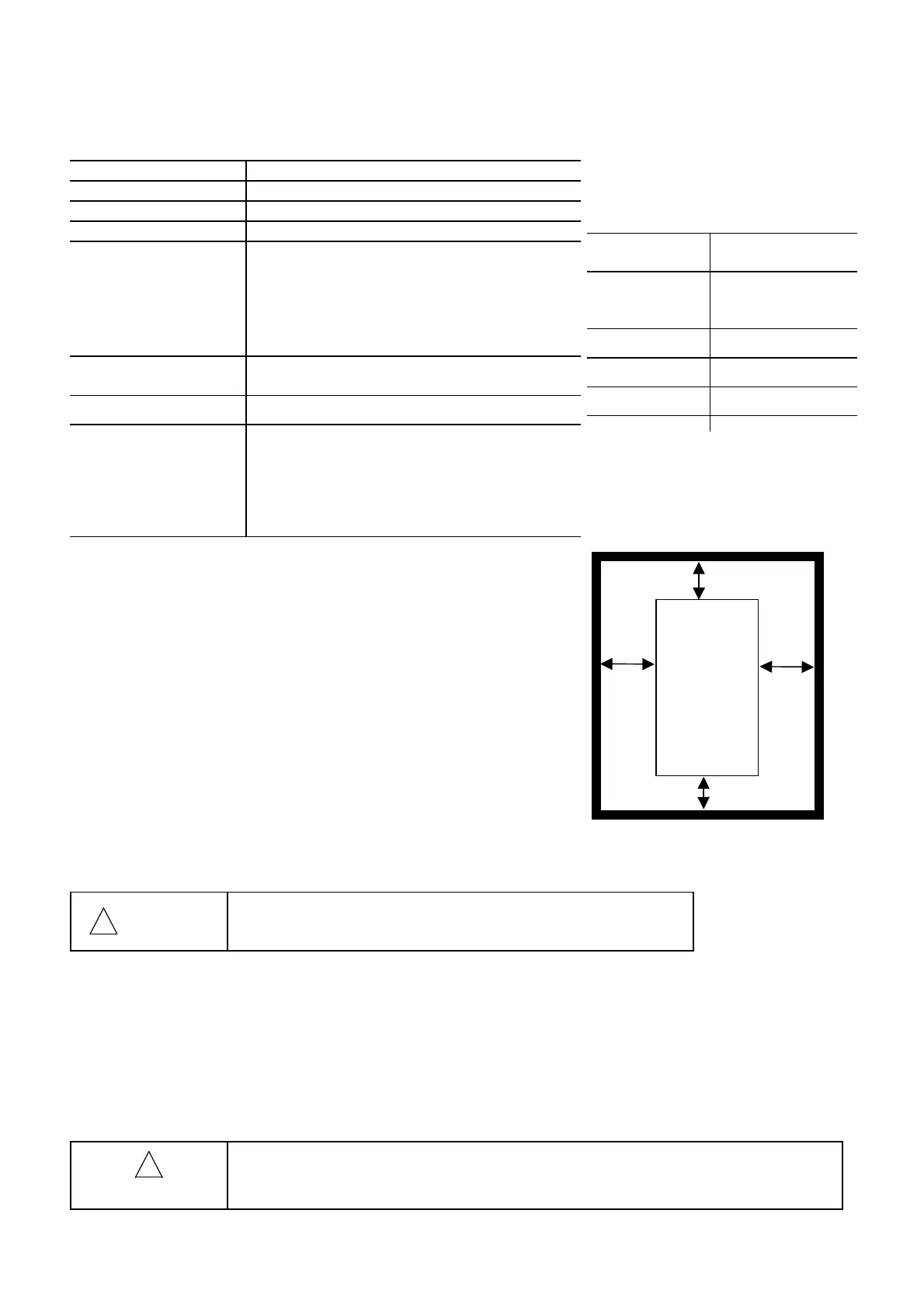
(2) Allow clearances for cooling wind shown in Fig. 2-2-1
to cool down the inverter which generates heat
during operation. The generated heat is radiated
upward. Do not install the inverter below a heat
sensitive device.
(3) The temperature of the heat sink rises to about 90
degrees C during operation of the inverter. Mount the
inverter on a base made of a material withstanding
the temperature rise.
!
!!
!
WARNING
Install the inverter on a nonflammable material such as
metal.
Otherwise fire could occur.
(4) When installing the inverter inside a control panel or the like, take full consideration for
ventilation so that the ambient temperature of the inverter does not exceed the specification
requirements. Do not install the inverter in a poorly ventilated small enclosure.
(5) When storing multiple inverters inside a single unit or inside a control panel, horizontal
installation is recommended to reduce mutual temperature effects. When an vertical layout is
adopted for an unavoidable reason, install a partition plate or the like between inverters to isolate
the heat of the lower inverter.
!
!!
!
CAUTION
Do not allow lint, paper, wood chips, dust, metallic chips or other foreign matter in
the inverter or do not allow them attached to the heat sink.
Otherwise fire or an accident could occur.
Fig. 2-2-1
Table 2-1-2 Output attenuation ratio
in relation to altitude
Altitude
Output current
attenuation ratio
1000 m or
less
1.00
1000-1500m 0.97
1500-2000m 0.95
2000-2500m 0.91
Above
Main body
FVR-E11S
10mm
100mm
Below
Left
10mm
100mm
Right

 Loading...


