2-3
■
■■
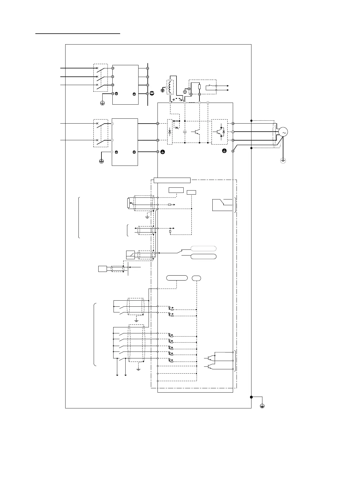
■ Basic connection diagram
U
L2/N
L1/L
Power supply (*1)
Single-phase
200 to 240 V
50/60 Hz
Molded case
circuit breaker
(MCCB) or earth
leakage circuit
breaker (ELCB)
Power supply (*1)
Three-phase
380 to 480 V
50/60 Hz
G
EFL-E11-7
FWD
REV
X1
X2
X3
X4
X5
CM
13
12
11
C1
FM
V
W
P1
P(+) DB N(-)
M
<Y1E>
<Y2E>
<CMC>
G
Motor
Grounding
terminal
SR
10Vdc
(-)
(+)
22~27Vdc
Pulse output
Control circuit part
Analog frequency meter
0 to 50Hz
FM(*2)
Current input
for setting
4 to 20mAdc
A voltage signal (0 to +10 Vdc
or 0 to +5 Vdc) can be supplied
to terminals [12] and [11]
instead of a potentiometer.
Potentiometer (*2)
DC reactor
DCR (*2)
External braking resistor (*2)
(*4)
P
DB
2
1
Transistor output
Digital input (*2)
Analog
input
Alarm relay output
30
30A
30B
30C
3
2
1
Grounding
terminal
(P24)
(THR)
(*3)
Digital
frequency meter
(pulse counter)
(*2)
50Hz
22kohm
FM
Analog output
250ohm
To change the FM terminal to
pulse outputs, change SW1 on
the control board and change
F29.
(P24) (THR)
(When X5 assigned to THR)
3
P24
L1/R
L3/T
L2/S
L
N
L'
N'
EFL-E11-4
G
L1'
L2'
L3'
0V
L1
L2
L3
(*3)
Electric cabinet
Armoured
or
screened
cable
EMC compliance filter (*2)
EMC compliance filter (*2)
CM
FVR-E11S-EN
CM
CM
SW1
*1) Supply a source voltage
voltage of the inverter.
*2) Optional part. Use when
necessary.
*3) Peripheral equipment.
Use when necessary.
*4) To connect a DC reactor
and P (+) terminals.

 Loading...


