3-1
3. Operation
3-1 Inspection and Preparation Before Operation
Check the following before starting operation.
(1) Check if connection is correct.
Especially check if the power cables are connected to
inverter output terminals U, V and W and that the
grounding cable is grounded without fail.
(2) Check for short circuits between terminals and exposed
live parts and ground faults.
(3) Check for loose terminals, connectors and screws.
(4) Check if the motor is separated from mechanical equipment.
(5) Turn the switches off so that the inverter does not start or operate erroneously at power-on.
(6) After the power is turned on, check the following.
a. Check if the keypad panel shows an alarm.
b. Check if the fan built in the inverter rotates. (1.5 kW or above)
!
!!
!
WARNING
• Be sure to install the terminal cover before turning the power on.
Do not remove the cover during power application.
• Do not operate switches with wet hands.
Otherwise electric shock could occur.
3-2 Operation Method
There are various operation methods. Refer to chapter 4 "Keypad Panel" and chapter 5 "Selecting
Functions" to select the method most suitable for the purpose and operation specification. Table
3-2-1 shows general operation methods.
3-3 Test Operation
After checking for errors in section 3-1, perform a
test operation.
In the factory shipment state, the inverter is in the
keypad panel operation mode.
(1) Turn the power on and check that the LED
blinks while indicating the 0.00 Hz frequency.
(2) Using the key, set the frequency to a
low frequency such as 5 Hz.
(3) To turn forward: F02 = 2
To reverse: F02 = 3
After setting the above, press the
RUN
key to
start operation. To stop, press the
STOP
key.
(4) Check the following points.
a. Check if the direction of rotation is correct.
b. Check for smooth rotation without motor humming or excessive vibration.
c. Check for smooth acceleration and deceleration.
(5) Referring to function code P04 Motor 1 (auto tuning), tune the motor constant.
When no abnormality is found, raise the operation frequency to check.
After checking for correct operation during the above test operation, start normal operation.
Caution 1: If any abnormality is found to the inverter or motor, immediately stop operation and
determine the cause referring to chapter 7 Troubleshooting.
Caution 2: If voltage is applied to the L1/R, L2/S and L3/T or L1/L and L2/N main circuit power
supply terminals even after the inverter stops, the inverter output terminals U, V and W
are live and you will be hit by electric shock when touching the terminals. As well, the
smoothing capacity is not discharged immediately after the power is turned off and it
takes time for the capacitor to be discharged.
To touch the electric circuit after turning the power off, check that the charge lamp is unlit
and check for safe voltage using a multimeter.
Operation
method
Frequency
setting
Operation
command
Operation
using keypad
panel
Keypad
panel keys
,
Keypad panel
keys
RUN
,
STOP
,
Operation
using external
signal terminal
Potentiometer
or analog
voltage,
current or
multistep
speed
operation
Contact input
(switch),
terminals
FWD-P24,
terminals
REV-P24
Table 3-2-1 General operation methods
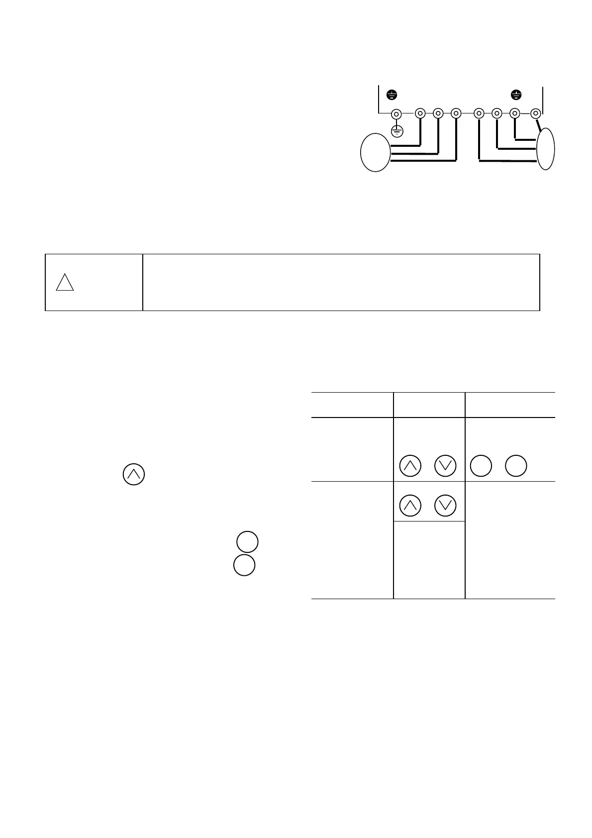
Fig. 3-1-1
Inverter connection diagram
Motor
Power
supply
Inverter
G L1/R L2/S L3/T U V W G
(L1/L) (L2/N)

 Loading...


