5-14
F09
Torque boost 1
This function is for motor 1. The following
options can be selected.
- Selection of load characteristics such as
automatic torque boost, square reduction
torque load, proportional torque load and
constant torque load.
- Correction of magnetic flux shortage of motor
in accordance with the voltage drop in low
frequency zone, and torque boost during low
speed operation (boosting of V/f
characteristics).
Setting range
Description of selection
0 Automatic torque boost characteristics
where the torque boost value of the
constant torque load is automatically
adjusted (refer to function code P04
"Motor 1 (“(Tuning)").
1 Square reduction torque characteristics
for fan and pump loads
2 Proportional torque characteristics for
intermediate load between the square
reduction torque and torque
characteristics.
3 to 31 Constant torque characteristics
Torque characteristics
<Square reduction torque characteristics>
<Proportional torque characteristics>
100%
Output frequency f
Base
frequency 1
1
2
0
Rated voltage 1
Output voltage V
<Constant torque characteristics>
100%
Output frequency f
Base
frequency 1
3
31
0
19%
Rated voltage 1
Output voltage V
Note) When the torque boost value is excessively
large, the motor is excessively excited in the
low speed zone at all types of characteristics.
If operation continues in such a state, the
motor may be overheated. Set a value
according to the characteristics of the driven
motor.
F10
Electronic thermal overload relay 1
(Select)
F11 Electronic thermal overload relay 1
(Level)
F12
Electronic thermal overload relay 1
(Thermal time constant)
The electronic thermal overload relay watches the
output frequency, output current and operation
time of the inverter to prevent the motor from
overheat. The protective function becomes active
when 150% of the set amperage flows for the time
set at F12 (thermal time constant).
F10
Selection between active and inactive operation of
the electronic thermal overload relay and selection
of the target motor are made. When the general
purpose motor is selected, the operation level is
low at low revolution speeds according to the
cooling characteristics of the motor.
Setting: 0 Inactive
1 Active (for general purpose motor)
2 Active (for forced-ventilated motor)
F11
The operation level of the electronic thermal
overload relay is set in amperage. Enter the
value 1.0 to 1.1 times rated current of the motor.
The setting range is 20 to 135% of the rated
inverter current.
Output frequency f0 (Hz)
fe×0.33
fe
100
When F10 is 2
(%)
(When F10 is 1)
Graph of relationship between operation
level current and output frequency
fe= fb (fb<60Hz)
60Hz (fb≧60Hz)
fb: Base frequency
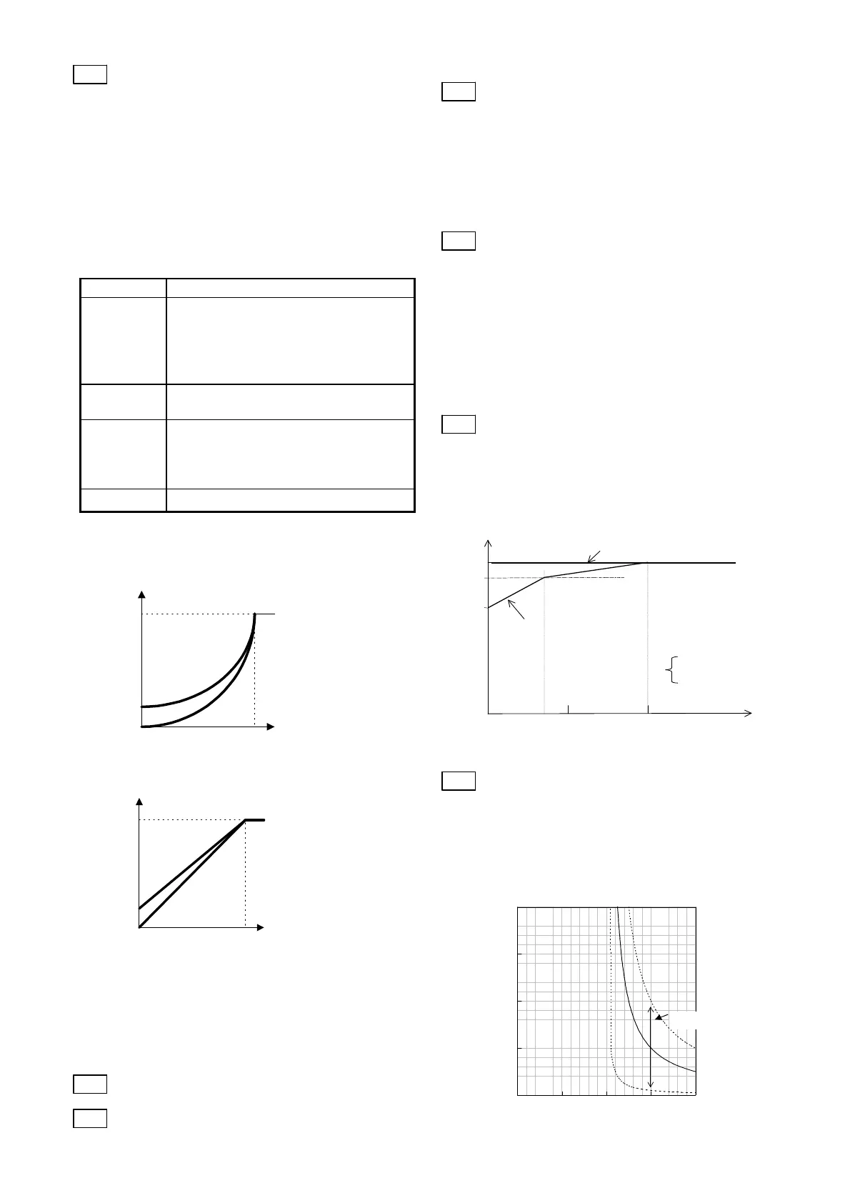
F12
Set the time since 150% of the operation level
current flows continuously until the electronic
thermal overload relay functions.
Setting range: 0.5 to 10.0 min.
Typical current - operation time
characteristics
0
5
10
15
20
0 50 100 150 200
Operation time (min.)
F12=0.5
F12=10
F12=5
Set by F12
((O utp ut current) / (O peration le vel current)) x 100 (%)

 Loading...


