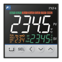
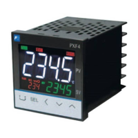
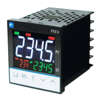
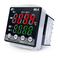
Thank you for purchasing the Fuji module type temperature controller.
2QFH\RXKDYHFRQ¿UPHGWKDWWKLVLVWKHSURGXFW\RXRUGHUHGSOHDVHXVHLWLQDFFRUGDQFHZLWKWKHIROORZLQJ
instructions.
)RUGHWDLOHGLQIRUPDWLRQRQRSHUDWLQJWKLVHTXLSPHQWSOHDVHUHIHUWRWKHVHSDUDWHXVHUVPDQXDO
,QDGGLWLRQSOHDVHNHHSWKLVLQVWUXFWLRQPDQXDOZLWKLQHDV\UHDFKRIWKHDFWXDOSHUVRQXVLQJWKLVHTXLSPHQW
&RQ¿UPLQJ6SHFL¿FDWLRQVDQG$FFHVVRULHV
Before using the product, confirm that it
matches the type ordered.
(For model code, please refer to page 23.)
&RQ¿UPWKDWDOORIWKHIROORZLQJDFFHVVRULHVDUH
included.
Temperature Controller 1 unit
Instruction Manual 1 copy
Mounting bracket 1 pc
Waterproof packing 1 pc
5HODWHG,QIRUPDWLRQ
5HIHUWRWKHIROORZLQJ UHIHUHQFH PDWHULDOV
for details about the items described in this
manual.
Document Reference No.
Data sheet EDS11-178
Micro Controller (Model: PXF)
Operation Manual
INP-TN5A2400-E
Micro Controller (Model: PXF)
Communication Functions
Manual (MODBUS)
INP-TN5A2227-E
7KHODWHVWPDQXDOVFDQDOVREHGRZQORDGHGDW
WKHIROORZLQJ85/
KWWSZZZIXMLHOHFWULFFRPSURGXFWVLQVWUXPHQWV
3OHDVH5HDG)LUVW6DIHW\,QIRUPDWLRQ
3OHDVHUHDGWKLVVHFWLRQWKRURXJKO\EHIRUHXVLQJDQGREVHUYHWKHPHQWLRQHGVDIHW\ZDUQLQJVIXOO\
6DIHW\ZDUQLQJVDUHFDWHJRUL]HG DV ³:DUQLQJ´RU³&DXWLRQ´)DLOXUHWRIROORZWKHLQVWUXFWLRQVPD\
UHVXOWLQDVDIHW\KD]DUG
Warning
PLVKDQGOLQJPD\OHDGWRPLQRURUVHULRXVSHUVRQDOLQMXU\¿UHDQGRUSURSHUW\GDPDJH
Caution
0LVKDQGOLQJPD\FDXVHLQMXU\WRWKHXVHURUSURSHUW\GDPDJH
,IWKHHTXLSPHQWLVXVHGLQDPDQQHUQRWVSHFL¿HGE\WKHPDQXIDFWXUHUWKHSURWHFWLRQSURYLGHGE\WKH
equipment may be impaired.
:DUQLQJ
/LPLWDWLRQVLQ8VH
7KLVSURGXFWLVDWHPSHUDWXUH FRQWUROOHU ZKLFKZDVGHYHORSHGGHVLJQHG DQG PDQXIDFWXUHGRQWKH
SUHPLVHWKDWLWZRXOGEHXVHGIRUJHQHUDOPDFKLQHU\
In particular, if this product is to be used for applications that require the utmost safety as described
EHORZSOHDVHWDNHLQWRFRQVLGHUDWLRQRIWKHVDIHW\RIWKHHQWLUHV\VWHPDQGWKHPDFKLQHE\DGRSWLQJ
VXFKPHDQVDVDIDLOVDIH GHVLJQ DUHGXQGDQF\GHVLJQDV ZHOO DVWKHFRQGXFWLQJRISHULRGLFDO
inspections.
6DIHW\GHYLFHVIRUWKHSXUSRVHRISURWHFWLQJWKHKXPDQERG\
'LUHFWFRQWURORIWUDQVSRUWDWLRQHTXLSPHQW
$LUSODQHV
6SDFHHTXLSPHQW
$WRPLFHTXLSPHQWHWF
3OHDVHGRQRWXVHWKLVSURGXFWIRUDSSOLFDWLRQVZKLFKGLUHFWO\LQYROYHKXPDQOLYHV
&$87,21
7KHFRQWHQWVRIWKLVPDQXDODUHVXEMHFWWRFKDQJHZLWKRXWQRWLFH
7KLVPDQXDOLVFRPSOLHGZLWKSRVVLEOHFDUHIRUWKHSXUSRVHRIDFFXUDF\KRZHYHU
)XML(OHFWULFVKDOOQRWEH KHOG OLDEOHIRUDQ\GDPDJHV LQFOXGLQJ LQGLUHFWGDPDJHFDXVHGE\
typographical errors,
absence of information or use of information in this manual.
,QVWDOODWLRQDQG:LULQJ
Ź 7KLVHTXLSPHQWLVLQWHQGHGWREHXVHGXQGHUWKHIROORZLQJFRQGLWLRQV
Ambient temperature -10 °C to 50 °C
Ambient humidity 5+RUEHORZZLWKQRFRQGHQVDWLRQ
Overvoltage category II
by IEC 61010-1
Pollution degree 2
Recommended fuse
9$&$77LPH/DJIRUWR9$&3RZHUVXSSO\
9'&9$&$77LPH/DJIRU9'&9$&3RZHUVXSSO\
Usage environment Indoor use
Ź ,IDFFHVVLEOH6DIHW\([WUD/RZ9ROWDJH6(/9FLUFXLWVDUHWREHFRQQHFWHGWR6LJQDOLQSXWWHUPLQDO
SSR Drive output terminal, Current output terminal or Communication (RS485) terminal, ensure
WRSURYLGHDEDVLFLQVXODWLRQ EHWZHHQWKH6(/9FLUFXLWVDQGWKHVHWHUPLQDOV )RUH[DPSOHXVH
WUDQVIRUPHUZKLFKKDVDEDVLF LQVXODWLRQ RUKLJKHUGHJUHHRI LQVXODWLRQ7KHEDVLF LQVXODWLRQ
requires a clearance at least 1.5 mm and a creepage of at least 3.0 mm. If such insulation is not
SURYLGHGWKH8/DQG(1VDIHW\FRPSOLDQFHPD\EHFRPHLQYDOLG
Ź)RU9 '&$& SRZHUVXSSO\PRGHOLI WKH HTXLSPHQWLVFRQQHFWHGWR WKH 6DIHW\([WUD/RZ
9ROWDJH6(/9FLUFXLWDEDVLFLQVXODWLRQ PXVWEHSURYLGHGEHWZHHQWKH 6(/9 FLUFXLW DQGWKH
SRZHULQSXWWHUPLQDOV2WKHUZLVHWKHSRZHULQSXWWHUPLQDOVPXVWEHFRQQHFWWR([WUD/RZ9ROWDJH
(/9FLUFXLWVRDVWRSUHYHQWWKHHOHFWULFVKRFN
Ź )RU&7LQSXWXVH&XUUHQW7UDQVIHUZKLFKKDVVSHFL¿FDWLRQDVVKRZQEHORZLQRUGHUWRSUHYHQWWKH
HOHFWULFVKRFNDQGVSUHDGRI¿UH
1) Over Voltage Category II
2) Pollution Degree 2
3) Required level of Insulating
%$6,&,168/$7,216833/<0(17$5<,168/$7,21
RU5(,1)25&(',168/$7,21
0D[LPXP9ROWDJHOLQHWRQHXWUDO 300Vac rms or 300Vdc
About safety standard
3OHDVHREVHUYHWKHIROORZLQJLQVWUXFWLRQVWRPHHWWKHUHTXLUHPHQWVRIVDIHW\VWDQGDUG
Failure to observe these instructions violates safety standards. (This product is not a safety equipment.)
………………………………………………………………………………………………………………………………
Ɣ,QVWDOODUHFRPPHQGHGIXVHZKLFKLVVSHFL¿HGLQWKHLQVWUXFWLRQPDQXDOEHWZHHQWKHH[WHUQDOPDLQSRZHU
(mains circuit) and this equipment.
Ɣ,IDFFHVVLEOH6DIHW\([WUD/RZ9ROWDJH6(/9FLUFXLWVDUHWREHFRQQHFWHGWR6LJQDOLQSXWWHUPLQDO665
Drive output terminal, Current output terminal or Communication (RS485) terminal, ensure to provide a
EDVLFLQVXODWLRQEHWZHHQWKH6(/9FLUFXLWVDQGWKHVHWHUPLQDOV)RUH[DPSOHXVHWUDQVIRUPHUZKLFKKDVD
basic insulation or higher degree of insulation). The basic insulation requires a clearance at least 1.5 mm
DQGDFUHHSDJHRIDWOHDVWPP,IVXFKLQVXODWLRQLVQRWSURYLGHGWKH8/DQG(1VDIHW\
compliance may become invalid.
Ɣ:KROHWKLVHTXLSPHQWPXVWEHPRXQWHGLQDQHQFORVXUHLQRUGHUWRSUHYHQWWKHHOHFWULFVKRFNDQGVSUHDG
RI¿UH
Ɣ%HVXUHWRLQVWDOODQDSSURSULDWHH[WHUQDOSURWHFWLYHFLUFXLWWRSUHYHQWH[FHVVLYHWHPSHUDWXUHULVHHWF
Ɣ:KHQSHUIRUPLQJZLULQJZRUNEHVXUHWRWXUQWKHSRZHURIIDQGWRZHDUSURWHFWLRQJORYHVRUVDIHW\JODVVHV
to prevent an electric shock.
Ɣ6HWSURSHUSDUDPHWHULQSXWVLJQDOVZKLFKFRUUHVSRQGWRHDFKLQSXWWREHFRQQHFWHG%HFDUHIXOQRWWR
FRQIXVHYROWDJHLQSXWZLWKFXUUHQWLQSXWRUYLFHYHUVD
Ɣ'RQRWXVHWKLVHTXLSPHQWIRUWKHPHDVXUHPHQWRIFLUFXLWVZKLFKIDOOVXQGHUPHDVXUHPHQWFDWHJRULHV,,,,,
or IV.
Ɣ'RQRWXVHWKLVHTXLSPHQWIRUPHDVXUHPHQWRIVLJQDOVWRZKLFKDYROWDJHRYHU9506RURYHU9'&LV
applied.
Ɣ,IWKHUHLVDULVNWKDWDQ\RQHPD\FRPHLQWRFRQWDFWZLWKWKHWHUPLQDOZKLOHWKHLQVWUXPHQWLVEHLQJ
HQHUJL]HGDWWDFKWKHWHUPLQDOFRYHURSWLRQDOWRSUHYHQWDQHOHFWULFVKRFN%HIRUHUHPRYLQJDWHUPLQDO
FRYHUWXUQRIIDOOWKHSRZHU
………………………………………………………………………………………………………………………………
Ź 1RWHWKDWWKHLQVXODWLRQFODVVIRUWKLVHTXLSPHQWLVDVIROORZV%HIRUHLQVWDOOLQJSOHDVHFRQ¿UPWKDW
the insulation class for equipment meets usage requirements.
Internal circuit
Process value input
Remote SV input
CT input
Control output 1
(SSR drive, current, voltage)
Control output 2
(SSR drive, current, voltage)
Control output 1
(SSR drive, current, voltage)
Control output 2
(SSR drive, current, voltage)
Digital input 1 to 3
Communication (RS-485)
Power supply (100 to 240V AC)
Control output 1 (relay contact)
or
Motorized valve OPEN output
Control output 2 (relay contact)
or
Motorized valve CLOSE output
Alarm output 1
(relay contact)
Alarm output
1 to 3
(relay contact)
Alarm output 2
(relay contact)
Control output 1 (relay contact)
or
Motorized valve OPEN output
Control output 2 (relay contact)
or
Motorized valve CLOSE output
Alarm output 1
(relay contact)
Alarm output
1 to 3
(relay contact)
Alarm output 2
(relay contact)
Basic insulation (1500 V AC) Functional insulation (500 V AC) No insulation
(1) (2) (1) (2)
Internal circuit
Process value input
Remote SV input
CT input
Digital input 1 to 3
Communication (RS-485)
Power supply (24V DC/24V AC)
(1):When the 9th code is "J" AL 1 and 2: independent common
(2):When the 9th code is other than "J" AL 1 to 3: shared common
Ɣ$SRZHUVZLWFKRUDFLUFXLWEUHDNHUVKRXOGEHLQVWDOOHGZLWKLQWKHSRZHUVXSSO\IDFLOLW\
Ɣ$SRZHUVZLWFKRUDFLUFXLWEUHDNHUVKRXOGEHSURSHUO\LQVWDOOHGZLWKLQHDV\UHDFKRIDQRSHUDWRU
Ɣ$SRZHUVZLWFKRUDFLUFXLWEUHDNHUVKRXOGEHLGHQWL¿HGDVWKHRQHIRUWKLVSURGXFW
Ɣ(OHFWULFDOZLULQJPXVWEHPDGHE\WKHTXDOL¿HG SHUVRQQHORQO\DQGLQDFFRUGDQFH ZLWK \RXUORFDO
and national standards.
Ɣ)RUSRZHUVXSSO\ZLULQJXVHZLUHHTXDOWR9YLQ\OLQVXODWHGZLUHRUDERYH
Ɣ7RSUHYHQWGDPDJHDQGIDLOXUHRIWKHHTXLSPHQWSURYLGHWKHUDWHGSRZHUYROWDJH
Ɣ7RSUHYHQWVKRFNDQGHTXLSPHQWIDLOXUHGRQRWWXUQWKHSRZHU21XQWLODOOZLULQJLVFRPSOHWH
Ɣ%HIRUHWXUQLQJRQSRZHUFRQ¿UPWKDWFOHDUDQFHVSDFHKDVEHHQVHFXUHGWRSUHYHQWVKRFNRU¿UH
Ɣ'RQRWWRXFKWKHWHUPLQDOZKLOHWKHPDFKLQHLVRQ'RLQJVRULVNVVKRFNRUHTXLSPHQWHUURUV
Ɣ1HYHUGLVDVVHPEOHFRQYHUWPRGLI\RUUHSDLUWKLV HTXLSPHQW 'RLQJVRULVNVDEQRUPDO RSHUDWLRQ
VKRFNRU¿UH
Ɣ,IDQ\IDLOXUHRFFXUVSOHDVHFRQWDFWWKHPDQXIDFWXUHUDQGUHWXUQWKHSURGXFW
Ɣ2XWSXWUHOD\LVWKHSDUWKDVDOLPLWHGOLIH:KHQRXWSXWUHOD\FRQWDFWFRPHVWRWKHHQGRILWVOLIHLW
might remain on-state, or off-state. For safety, use a protective circuit outside.
Ɣ7KH IDFWRU\GHIDXOWVHWWLQJRI WKLV HTXLSPHQWLVDVIROORZV &KDQJH WKHVHWWLQJDVQHFHVVDU\ VR
as the equipment to meet your application. Please note that the improper settings may result in
RYHUKHDWRUXQH[SHFWHGGDPDJH
For the details of operation, refer to the separate volume, "Operation Manual (INP-TN5A2400-E)".
Control output 1: heating control
Control output 2 (optional): cooling control
Alarm output 1 to 3 (optional): No function
Ɣ6\PEROVRQWKHLQVWUXPHQW
: Read this instruction manual thoroughly before using the product, and usethe product safely.
0DLQWHQDQFH
Ɣ:KHQ LQVWDOOLQJRUUHPRYLQJWKHHTXLSPHQW WXUQ WKHSRZHU2))2WKHUZLVHVKRFN RSHUDWLRQDO
errors or failures may be caused.
Ɣ3HULRGLFPDLQWHQDQFHLVUHFRPPHQGHGIRUFRQWLQXRXVDQGVDIHXVHRIWKLVHTXLSPHQW
Ɣ6RPHSDUWVLQVWDOOHGRQWKLVHTXLSPHQWKDYHDOLPLWHGOLIHDQGRUPD\GHWHULRUDWHZLWKDJH
Ɣ7KHZDUUDQW\SHULRGIRUWKLVXQLWLQFOXGLQJDFFHVVRULHVLVWKUHH\HDUVDIWHUWKHGDWHRIPDQXIDFWXUH
if the product is used properly.
Option
Name Quantity Order No.
Terminal cover 1 pc ZZPPXR1-A230
PC loader
communication cable
1 cable ZZP*TQ501923C3
Shunt resistor
1 pc ZZPPXR1-A190
- 1 -
Model : PXF4
Micro Control X
Instruction Manual
INP-TN2PXF4d-E
Global Sales Section
Instrumentation & Sensors Planning Dept.
1, Fuji-machi, Hino-city, Tokyo 191-8502, Japan
http://www.fujielectric.com
Phone: +81-42-514-8930 Fax: +81-42-583-8275
http://www.fujielectric.com/products/instruments/


 To Next Page
 General