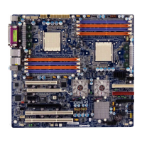
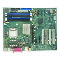
Board Installation
CD-In and AUC-IN (CD / AUX)
There are two connectors available for CD audio and AUX audio. Both connectors are 4-pin.
See the illustration below for pinouts.
Pin Signal
1
Audio_L
2
Audio_GND
3
Audio_GND
4
Audio_R
Front Panel Header (FP)
Normally, a chassis has some control or signal wires can be connected onto a motherboard for hard
drive LED, Power LED, power button, and reset button;
The front panel header has been implemented on D1808 for such purposes.
Signal Pin Pin Signal
GND
1 2
SPEAKER_OUT_L
SLP_LED_Anode
3 4
Key
Key
5 6
GND
PWR_LED_Anode
7 8
SPEAKER_OUT_H
PWR_LED_Anode
9 10
n.c.
GND
11 12
n.c.
+3.3V
13 14
Key
MSG_LED_Cathode
15 16
n.c.
Key
17 18
SCSI_LED_Cathode
+3.3V
19 20
SCSI_LED_Cathode
HD_LED_Cathode
21 22
n.c.
GND
23 24
Key
PWR_Button_L
25 26
GND
SLP_Button_L
27 28
GND
RESET_L
29 30
GND
10 A26361-D1808-Z120-1-7619, edition 1

 Loading...
