Do you have a question about the Fujitsu Siemens Computers D1691 and is the answer not in the manual?
Verification of all included motherboard package items.
Welcome message and overview of the purchased workstation solution.
Detailed list of all physical components and their capabilities.
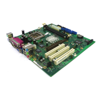
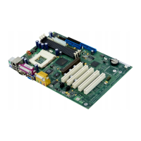
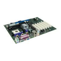
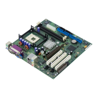
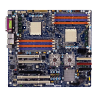
Visual representation of the motherboard's key components and connectors.
Guidelines and requirements for selecting and installing the CPU.
Information on compatible memory types and installation requirements.
Factors to consider when choosing a chassis for the motherboard.
Requirements and compatibility for power supply units.
Diagram identifying main components and connectors on the motherboard.
Explanation of jumper functions and their definitions for configuration.
Procedure for resetting CMOS settings using a specific jumper.
Details on 3-pin fan connectors for system cooling and monitoring.
Pinout description for connecting chassis front panel controls and LEDs.
Pinout details for connecting front panel USB ports.
Pinout description for connecting an external HDD activity LED.
Information on connecting Serial ATA hard drives and RAID configurations.
Instructions and tips for securely mounting the motherboard in the chassis.
Guidelines for selecting and installing compatible DDR-II memory modules.
Step-by-step instructions for correctly installing memory modules.
Detailed guide for installing Intel Xeon processors and their heatsinks.
Instructions for connecting IDE and Serial ATA drive cables.
Guidance on installing expansion cards into available slots.
How to connect peripherals like keyboards, mice, and printers.
Procedure for connecting the power supply unit to the motherboard.
Final checks and steps after completing hardware installation.
Information on accessing help within the BIOS setup utility.
Troubleshooting steps for issues encountered after BIOS changes.
Notes on potential differences in BIOS layout across systems.
Basic system time, date, and diskette configuration settings.
Configuration options for IDE and Native IDE drive modes.
Display of system BIOS version, build date, and hardware identifiers.
Access to detailed system configuration and performance tuning options.
Settings for fan speed control and monitoring system hardware.
Information display for realtime hardware monitoring sensors.
Configuration options for logging BIOS events and error messages.
Details and settings related to CPU type, speed, and threading.
Configuration options for the system chipset, including memory checking.
Enable or disable the integrated floppy disk controller.
Settings for Parallel ATA and Serial ATA interface modes.
Configuration options for the onboard SCSI controller.
Settings for the onboard LAN controller and latency timer.
Enable or disable the integrated audio controller.
Enable or disable the integrated IEEE 1394 controller.
Configuration options for USB 1.1, USB 2.0, and legacy support.
Settings for serial and parallel ports, including I/O addresses and modes.
Configuration options for PCI Express and PCI slots.
Settings for individual PCI device configurations and option ROMs.
Managing PCI/PNP IRQ assignments for legacy device compatibility.
Setup options for system passwords and boot security features.
Configuration settings for Advanced Power Management (APM) features.
Settings to control the system boot process and device priority.
Defines the order in which boot devices are checked.
Options for saving changes, discarding, or loading default settings.
Interpreting audible beep codes for system errors.
Information on using the BIOS flash utility for updates and downloads.
Information and resources for obtaining technical assistance and warranty service.
| Manufacturer | Fujitsu Siemens Computers |
|---|---|
| Model | D1691 |
| Form Factor | ATX |
| Socket | LGA775 |
| Memory Slots | 4 |
| Memory Type | DDR2 SDRAM |
| Expansion Slots | 1x PCIe x16, 2x PCIe x1, 3x PCI |