EasyManua.ls Logo

Fujitsu AJ**A72LBTF User Manual

Fujitsu AJ**A72LBTF
36 pages
To Next Page IconTo Next Page
Page #1 background imageLoading...
Page #1 background image
En-1
English
Refrigerant
R410A
INSTALLATION INSTRUCTION SHEET
(PART NO. 9374241033)
Multi Air Conditioning System
for Buildings (VRF System)
OUTDOOR MODEL
AJ A72LBTF
MASTER AJ
A90LBTF
AJ
126LBTF
AJ
A72UBTF
SLAVE AJ
A90UBTF
AJ
126UBTF
Contents
1. SAFETY PRECAUTIONS ......................................................................... 2
2. PRECAUTIONS FOR USING THE ALTERNATIVE REFRIGERANT ....... 3
3. ACCESSORIES ........................................................................................ 4
4. INSTALLATION WORK ............................................................................ 5
4.1. SELECTING AN INSTALLATION LOCATION .............................................. 5
4.2. TRANSPORTING THE PRODUCT .............................................................. 6
4.3. INSTALLATION DIMENSIONS ..................................................................... 7
4.4 INSTALLATION THE UNIT ........................................................................... 9
4.5. SYSTEM LAYOUT ...................................................................................... 10
4.6. PIPE SELECTION...................................................................................... 11
4.7. PIPE INSTALLATION ................................................................................. 12
4.8. INSTALLING INSULATION ........................................................................ 17
4.9. DRAIN PROCESSING ............................................................................... 17
4.10. ELECTRICAL WIRING ............................................................................... 18
4.11. FIELD SETTING ........................................................................................ 23
5. CHARGING WITH REFRIGERANT ........................................................ 28
5.1. SEALING TEST ......................................................................................... 28
5.2. VACUUM PROCESS ................................................................................. 29
5.3. ADDITIONAL CHARGING ......................................................................... 29
6. TEST RUN ............................................................................................... 31
6.1. PRE-TEST RUN CHECK ITEMS ............................................................... 31
6.2. TEST RUN METHOD ................................................................................. 31
6.3. CHECKLIST ............................................................................................... 31
7. ERROR DISPLAY ................................................................................... 32
7.1. NORMAL OPERATION MODE .................................................................. 32
7.2. ERROR OPERATION MODE ..................................................................... 33
8. PUMP DOWN .......................................................................................... 34
9. OPTION PARTS ......................................................................................35
10. INFORMATION ....................................................................................... 36
9374241033_IM_en_p01-17.p65 26/8/2008, 18:231
Question and Answer IconNeed help?

Do you have a question about the Fujitsu AJ**A72LBTF and is the answer not in the manual?

Fujitsu AJ**A72LBTF Specifications

General IconGeneral
Cooling Capacity7.2 kW
Heating Capacity8.0 kW
Power Supply220-240V, 50Hz
Energy Efficiency Ratio (EER)3.21
Coefficient of Performance (COP)3.61
RefrigerantR32
Indoor Unit Noise Level49 dB(A)

Summary

SAFETY PRECAUTIONS

PRECAUTIONS FOR USING THE R410A REFRIGERANT

ACCESSORIES

INSTALLATION WORK

SELECTING AN INSTALLATION LOCATION

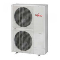
Guidelines for choosing a suitable installation site, considering weight, ventilation, access, and environmental factors.

TRANSPORTING THE PRODUCT

Procedures for safely moving the outdoor unit using ropes or forklifts, with precautions to prevent damage.

INSTALLATION DIMENSIONS

Specifies required clearances and dimensions for single and multiple unit installations to ensure proper operation and access.

INSTALLATION THE UNIT

Instructions for securely mounting the outdoor unit, including anchor bolt placement, base requirements, and vibration damping.

SYSTEM LAYOUT

Details on connecting multiple outdoor units to indoor units, including pipe length and height difference limitations.

PIPE SELECTION

Guidance on selecting appropriate pipe materials and diameters based on unit model, capacity, and connection configuration.

PIPE INSTALLATION

Procedures for pipe brazing and flare connections, emphasizing safety, proper techniques, and material compatibility.

INSTALLING INSULATION

Instructions for selecting and applying insulation material to refrigerant pipes to prevent condensation and dripping.

DRAIN PROCESSING

Methods for properly installing drain pipes and channels to manage condensate water from the outdoor unit.

ELECTRICAL WIRING

Critical warnings and procedures for safe and correct electrical wiring, including power supply, breakers, and grounding.

FIELD SETTING

Instructions for configuring DIP switches and rotary switches on the outdoor unit for proper system operation and addressing.

CHARGING WITH REFRIGERANT

SEALING TEST

Procedure to check for leaks in the refrigerant piping system using nitrogen gas under pressure.

VACCUM PROCESS

Steps for evacuating air and moisture from the refrigerant system to ensure optimal performance and prevent issues.

ADDITIONAL CHARGING

Guidelines for calculating and adding the correct amount of R410A refrigerant using an electronic scale and liquid pipe.

TEST RUN

PRE-TEST RUN CHECK ITEMS

Checklist of essential pre-operation checks, including gas leakage, refrigerant charge, wiring, and DIP switch settings.

TEST RUN METHOD

Procedures for performing test runs on the entire system or individual indoor units to verify correct operation.

CHECKLIST

Criteria for verifying correct operation during the test run, including pressure values, drain discharge, and temperature differences.

ERROR DISPLAY

NORMAL OPERATION MODE

Interpretation of LED indicators during normal system operation, indicating status like idling, cooling, or heating.

ERROR OPERATION MODE

Troubleshooting guide detailing error codes indicated by LED patterns for various system faults and sensor issues.

PUMP DOWN

OPTION PARTS

INFORMATION

Related product manuals