En-23
4.11. FIELD SETTING
CAUTION
Discharge the static electricity from your body before setting up the DIP switches.
Never touch the terminals or the patterns on the parts that are mounted on the board.
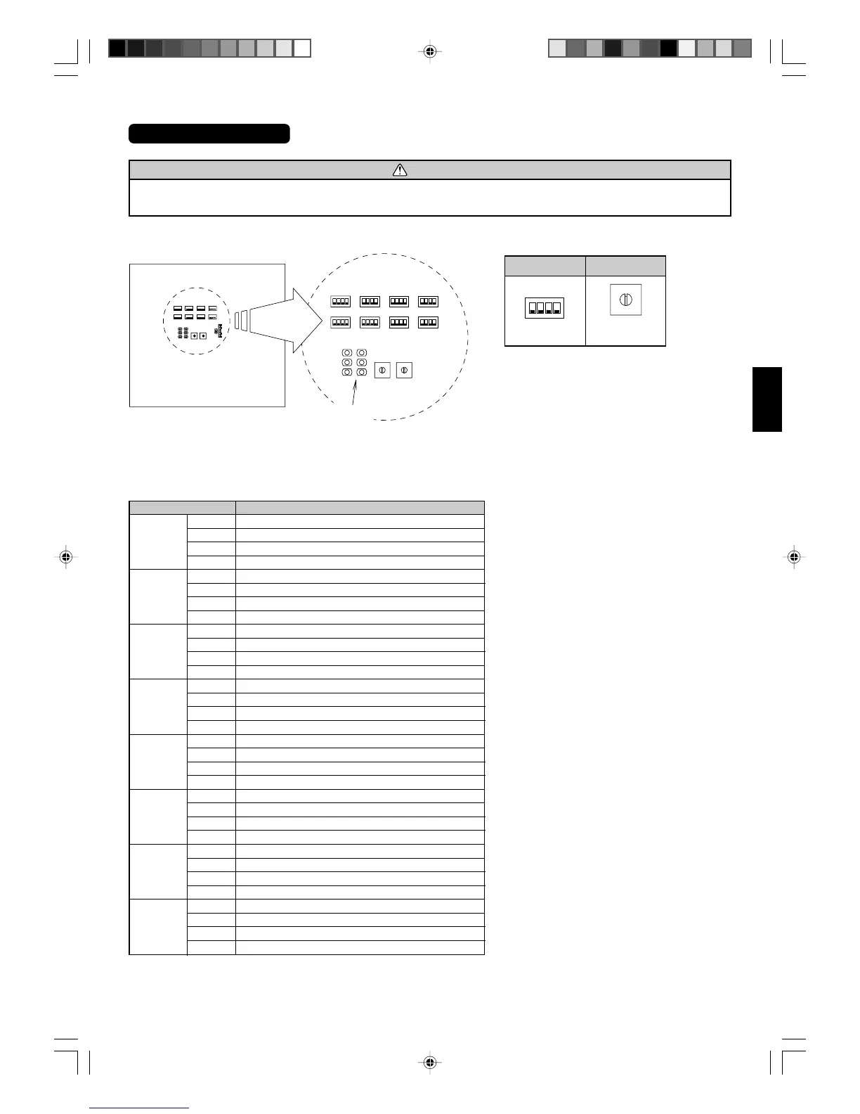
Fig. 4.11-1, Fig. 4.11-2 shows the positions of the switches on the board of the outdoor unit.
4.11.1. SWITCH SETTING
DIP switch Function
SW1
1 Test run (cooling)
2 Test run (heating)
3 Pump down operation
4 Forbidden
SW2
1 Silent operation mode
2 Falling protection fan mode
3 Sequential start shift switch 1
4 Sequential start shift switch 2
SW3
1 Outdoor unit capacity switch 1
2 Outdoor unit capacity switch 2
3 Outdoor unit address switch 1
4 Outdoor unit address switch 2
SW4
1 Slave unit connection number switch 1
2 Slave unit connection number switch 2
3 Forbidden
4 Error reset
SW5
1 Cooling ability shift switch 1
2 Cooling ability shift switch 2
3 Heating ability shift switch 1
4 Heating ability shift switch 2
SW6
1 Piping length switch 1
2 Piping length switch 2
3 Forbidden
4 Forbidden
SW7
1 Model information switch 1
2 Forbidden
3 Indoor unit small capacity switch
4 Forbidden
SW10
1 Forbidden
2 Forbidden
3 Forbidden
4 Forbidden
Table 4.11-1 DIP Switch Setup
LED lamp
SW1 SW2 SW3 SW4
SW5 SW6 SW7
SW9 SW8
SW10
Outdoor board
Fig. 4.11-1
ON
OFF
1234
0
F
D
C
B
A
9
8
7
6
5
4
3
2
1
Fig. 4.11-2 Detail of switch
DIP switch Rotary switch
Position
shown in “0”
9374241033_IM_en_p18-36.p65 26/8/2008, 18:2323