En-13
NO GOOD
NO GOOD NO GOOD
Horizontal
line
VIEW C
Outdoor
unit side
H
1 = 0 mm –
10 mm
(α
1 : 0° – 1°)
β
1: -10° – 10°
Gas pipe
Liquid pipe
Horizontal
line
VIEW D
Outdoor
unit side
H
2 = 0 mm –
10 mm
(α
2 : 0° – 1°)
β
2: -10° – 10°
Vertical
line
Horizontal
line
4.7.3. INDOOR UNIT PIPE CONNECTIONS
CAUTION
Separation tube
Horizontal Vertical
OK
A : Outdoor unit or Refrigerant branch kit
B : Indoor unit or Refrigerant branch kit
Header
C
H
1
α1
β1
D
H
2
α
2
β
2
OK
• Do not connect a separation tube after a header.
• Leave the distance 0.5 m or more for straight part to branch tube and header.
• For details, refer to the Installation Instruction Sheet of each part.
A
B
AB
A
B
Main pipe
0.5 m or more
To indoor
unit
0.5 m or more
To indoor
unit
4.7.4. PIPE ROUTING DIRECTION
CAUTION
• Be careful not to deform or scratch the panel while opening the knockout holes.
• After opening the knockout holes, deburr the edges to prevent them from cutting the wires.
Horizontal line
or
±15°
To indoor unit
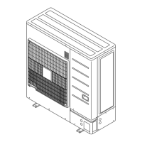
Pipes can be connected from 4 directions. (Figs. 4.7-2, 3, 4)
(Knockout holes are provided so that pipes can be connected from all 4 different directions.)
Fig. 4.7-2 Knockout
position
Fig. 4.7-3 Detail of knockout position (front/side/rear)
Front
Rear
98
220 22
35
13 80
80
50156
120119
141
39
139
39
Knockout hole
Knockout hole
Knockout hole
[Rear][Front] [Side]
Fig. 4.7-4 Knockout
position in bottom
210
30
194
36
75
Knockout hole
Right
or
Header
Separation tube
or
Header
Separation tube
To indoor
unit
To indoor
unit
9374241033_IM_en_p01-17.p65 26/8/2008, 18:2313

 Loading...
