Inverter cover
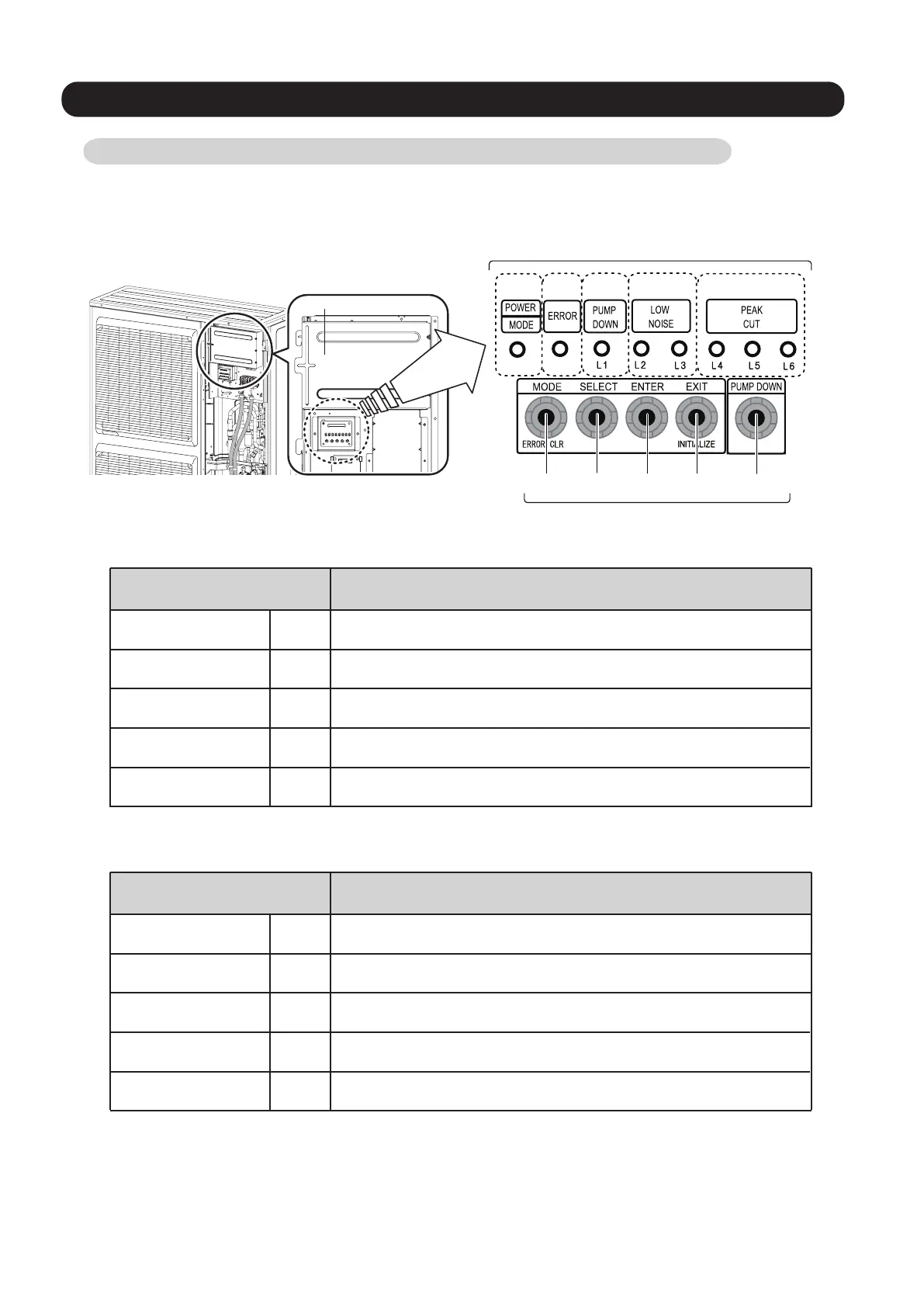
1-33. DESCRIPTION OF DISPLAY UNIT
•
Display lamp
Function or operation method
(1) POWER / MODE
Green
Lights on while power on. Local setting in outdoor unit or
error code is displayed with blink.
(2) ERROR
Red
Blinks during abnormal air-conditioner operation.
(3) PUMP DOWN
(L1)
Orange
Lights on during pump down operation.
(4) LOW NOISE MODE
(L2, L3)
Orange
Lights on during “Low noise” mo
d
e when local setting is activated.
(Lighting pattern of L2 and L3 indicates low noise level)
(5) PEAK CUT
(L4, L5, L6)
Orange
Lights on during “Peak cut” mode when local setting is activated.
(Lighting pattern of L4, L5 and L6 indicates peak cut level)
SW1 SW2 SW3 SW4 SW5
(1) (2) (3) (4) (5)
LED DISPLAY
Various settings can be adjusted by changing Push switches on the board of the outdoor unit.
( Excerpt from the "INSTALATION MANUAL" )
Switch
Function or operation method
SW1 To switch between “Local setting” and “Error code display”.
SW2
To switch between the individual “Local settings” and the
“Error code displays”.
SW3
To fix the individual “Local settings ” and the “Error code displays”.
SW4 To return to “Operation status display”.
SW5 To start the pump down operation.
MODE
SELECT
ENTER
EXIT / INITIALIZE
PUMP DOWN
PUSH SWITCH
1-33-1 Layout of Display Unit
01-27
 Loading...