Check that the “ERROR” LED blinks, then press the [Enter] button once.
For details, refer to the following table.
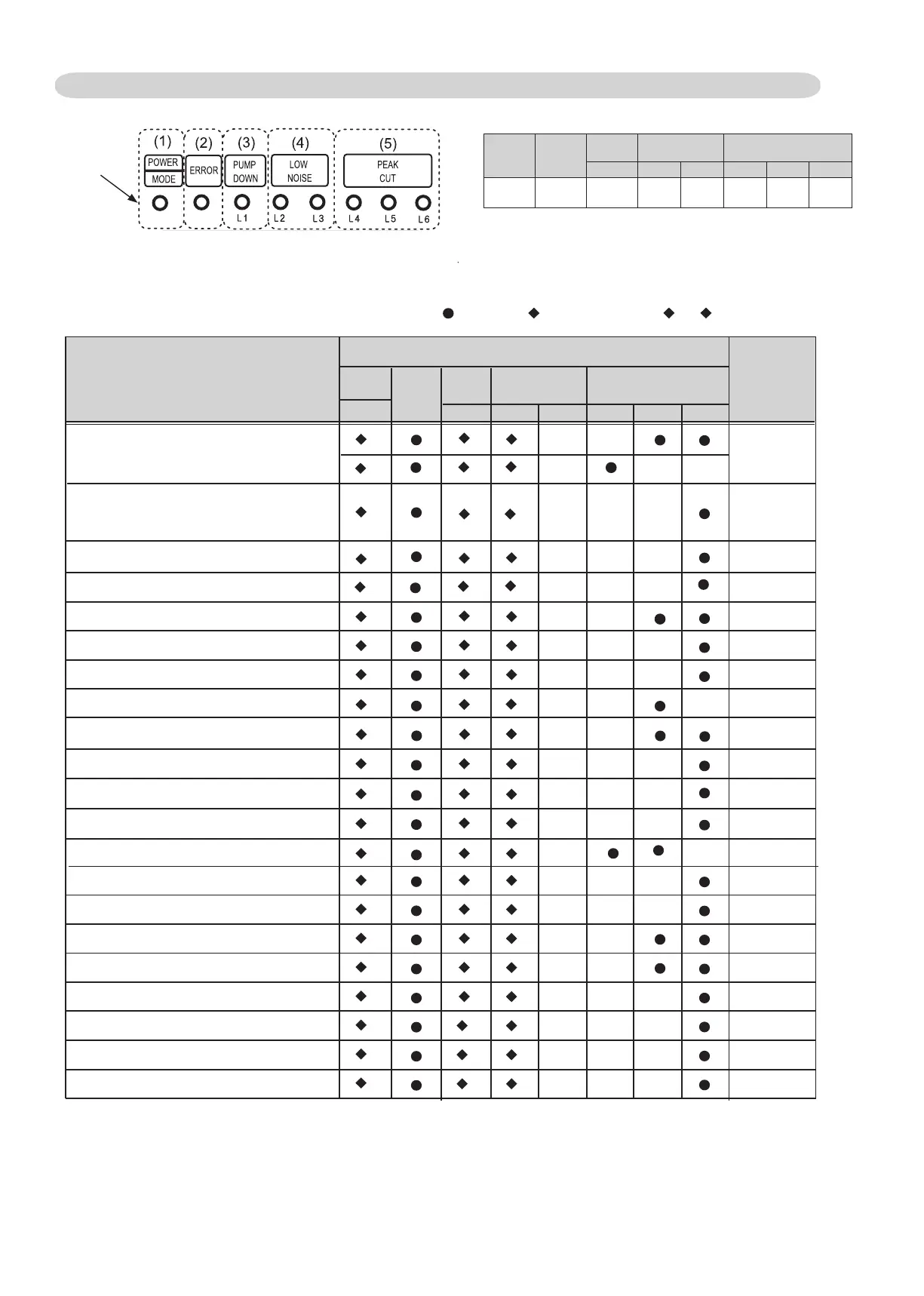
2-1-3 OUTDOOR UNIT DISPLAY
Error Contents
POWER
MODE
ERROR
Serial Communication Error
2
2
2
2
2
2
2
2
1
(L1) (L2) (L6)(L5)(L4)(L3)
IPM Error
Indoor Unit Error
Outdoor unit main PCB modelinformation error
Trip detection Error
Discharge Thermistor Error
Outdoor Thermistor Error
Current sensor Error
Compressor Thermistor Error
Compressor Control Error
Outdoor Unit Fan Motor 1 Error
Outdoor Unit Fan Motor 2 Error
4-way Valve Error
Discharge Temp. Error
Compressor Temp. Error
Low Pressure Error
2
2
2
2
2
2
2
2
2
1
5
6
2
6
5
7
1
18
7
2
7
3
7
4
8
4
9
4
9
5
9
7
9
8
9
9
01
1
01
3
01 5
51
Heat Ex. middle temp. sensor Error
Heat Ex. liquid temp. sensor Errorr
LED DISPLAY
PUMP
DOWN
LOW
NOISE
PEAK
CUT
Trouble
shooting
2
14
17
19
20
22
24
25
27
28
29
30
31
32
1, 3 ,6 - 8
10 - 13
1 ~ 15 : 1~ 15 Times Blinking
: Light ON: FFO thgiL :
2 : 2Times Blinking
You can determine the operating status by the lighting up and blinking of the LED lamp.
LED display part
Display when an error occurs.
POWER/
MODE
ERROR
PUMP
DOWN
LOW
NOISE
PEAK
CUT
(L1) (L2) (L3) (L4) (L5) (L6)
●
Blink
(Hi speed)
○ ○○○○○
Sign “
○
”: Lights off, “
●
”: Lights on
Check that the “ERROR” LED blinks, then press the “ENTER” button once.(1)
For details, refer to the following table.(2)
○
2
1
1
○ ○
○ ○ ○
○ ○ ○
○ ○ ○
○ ○ ○
○ ○ ○
○ ○ ○
○ ○ ○
○ ○ ○
○ ○ ○
○ ○
○ ○
○
○ ○
○
○ ○ ○
○ ○
○ ○
○ ○ ○
2
Inverter Error
6
3
15
○ ○ ○
Pressure sensor Error
2
8
6
26
○
○
33
○
○
2
7
3
21
○ ○
○
02-03
2
Heat Sink Temp. Sensor Error
7
7
23
○ ○ ○
 Loading...