– 57 –
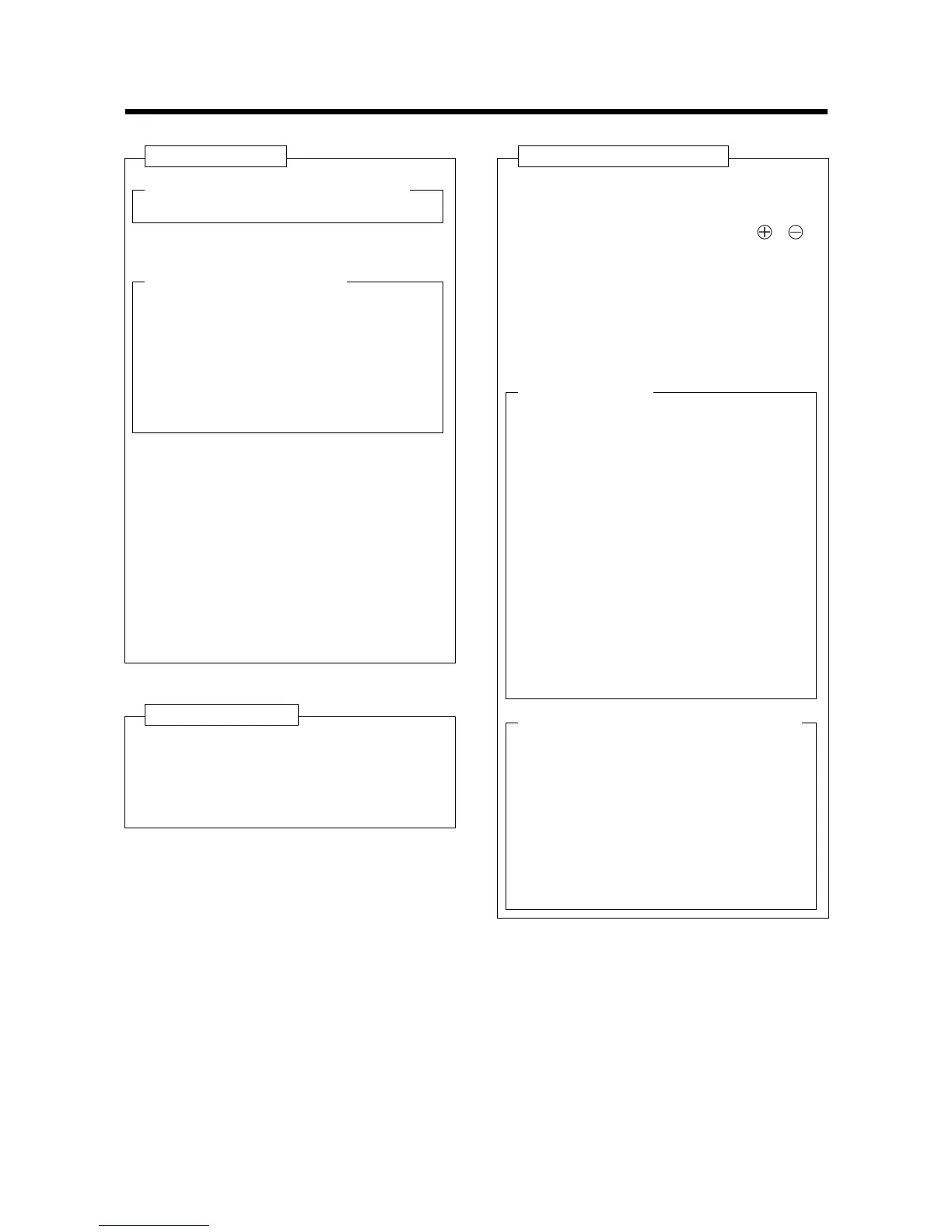
NAME OF PARTS
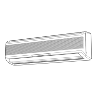
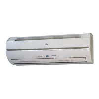
Fig. 1 Indoor Unit
e Remote Control Signal Receiver
u SWING Indicator Lamp (orange)
i Intake Grille (Fig. 4)
o Air Filter
!0 Air Flow Direction Louver
!1 Right-Left Louvers
(behind Air Flow Direction Louver)
!2 Drain Hose
!3 Power Supply Plug
!4 Power Supply Cord
!5 Air Cleaning Filter (optional)
q Operating Control Panel (Fig. 2)
w MANUAL AUTO button
r Indicator lamps (Fig. 3)
t OPERATION Indicator Lamp (red)
y TIMER Indicator Lamp (green)
• If the TIMER Indicator Lamp flashes when
the timer is operating, it indicates that a fault
has occurred with the timer setting (See
Page 70 Auto Restart).
Fig. 6 Remote Control Unit
@0 SLEEP button
@1 MASTER CONTROL button
@2 SET TEMP. / SET TIME button ( / )
@3 Signal Transmitter
@4 TIMER button
@5 FAN CONTROL button
@6 START / STOP button
@7 AIR FLOW DIRECTION button
@8 SWING LOUVER button
Rear side (Fig. 7)
@9 TIME ADJUST button
#0 ACL button
(located inside battery compartment)
#1 TEST RUN button
• This button is used when installing the unit,
and should not be used under normal condi-
tions, as it will cause the air conditioner’s
thermostat function to operate incorrectly.
• If this button is pressed during normal opera-
tion, the unit will switch to test operation
mode, and the Indoor Unit’s OPERATION
Indicator Lamp and TIMER Indicator Lamp
will begin to flash simultaneously.
• To stop the test operation mode, press the
START / STOP button to stop the air condi-
tioner.
Fig. 5 Outdoor Unit
!6 Intake Port
!7 Outlet Port
!8 Pipe Unit
!9 Drain port (bottom)
#2
Remote Control Unit Display (Fig. 8)
#3 Transmit Indicator
#4 Clock Display
#5 Operating Mode Display
#6 Timer Mode Display
#7 Fan Speed Display
#8 Temperature Set Display
#9 Timer Set Indicator
$0 Temperature Set Indicator