¢
Error status output
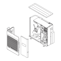
Indoor unit type Connector
Compact cassette —
Slim duct —
Wall mounted
ASU7RLF1, ASU9RLF1, ASU12RLF1, ASU15RLF1 CNB02
ASU9RLS2, ASU12RLS2, ASU15RLS2 CNB02
ASU7RLF, ASU9RLF, ASU12RLF —
ASU18RLF, ASU24RLF —
Floor AGU9RLF, AGU12RLF, AGU15RLF CN21
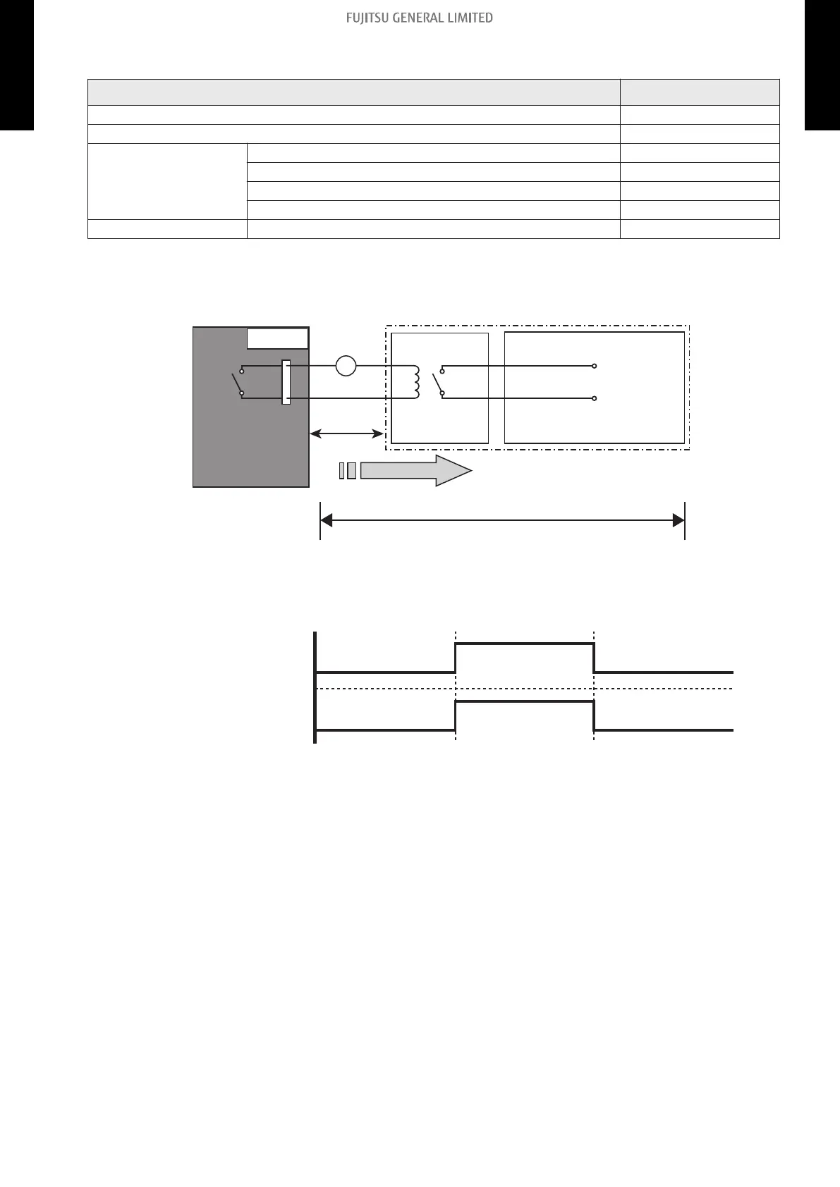
Air conditioner error status signal can be output.
• Circuit diagram example
Locally purchased
Example: Display
Indoor unit
control PCB *1
Connected unit
Example:
Relay unit
1
2
Signal
Relay
power
supply
V
Connector
33 ft
(10 m) *2
DC 24 V
– *1: PCB of communication kit is used for wall mounted type (ASU7RLF1, ASU9RLF1,
ASU12RLF1, and ASU15RLF1).
– *2: Make the distance from the PCB to the connected unit within 33 ft (10 m).
– Relay spec.: Max. DC 24 V, 10 mA to less than 500 mA.
On
Off
Error
Normal
Error status
Output signal
- 105 -
11-2. External output 11. External input and output
MULTI TYPE
2, 3, 4 ROOMS TYPE
MULTI TYPE
2, 3, 4 ROOMS TYPE

 Loading...