Do you have a question about the Fujitsu ASYA30LCC and is the answer not in the manual?
| Brand | Fujitsu |
|---|---|
| Model | ASYA30LCC |
| Category | Air Conditioner |
| Language | English |
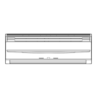
Dimensional details for ASYA24LCC/AOYR24LCC indoor units.
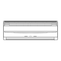
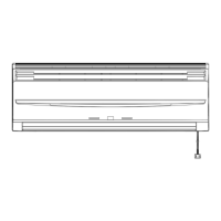
Dimensional details for ASYA30LCC indoor unit.
Dimensional details for ASYA24LCC/AOYR24LCC outdoor units.
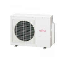
Dimensional details for AOYR30LCT outdoor unit.
Diagram of the refrigerant system for ASYA24LCC/AOYR24LCC models.
Diagram of the refrigerant system for ASYR30LCC/AOYR30LCT models.
Electrical circuit diagram for ASYA24LCC/AOYR24LCC models.
Electrical circuit diagram for ASYA30LCC/AOYR30LCT models.
Details on the cooling operation and capacity control.
Details on the heating operation and capacity control.
Details on the dry operation and indoor unit control.
Explanation of the automatic mode switching between operations.
Details on indoor fan speed and operation modes.
Details on outdoor fan speed settings for different modes.
Information on vertical and horizontal louver adjustments.
Explanation of compressor operation frequency and start-up control.
Details on OFF, ON, and PROGRAM timer functions.
Control method for the electronic expansion valve.
Procedure for performing test operation.
Mechanism to prevent compressor restart for 3 minutes.
Selection of four-way valve extension.
Functionality of automatic restart after power interruption.
Operation via indoor unit body button when remote is lost.
Process of preheating the compressor before operation.
Procedure for coil-dry operation to remove moisture.
Conditions and procedure for defrost operation.
Control of defrost operation when heating mode stops.
Details on various protection mechanisms including temperature, current, and pressure.
Lists and describes specialized tools required for R410A refrigerant handling.
Guidelines and warnings for installing systems with R410A refrigerant.
Important precautions for servicing equipment with R410A refrigerant.
Details about R410A refrigerant and its phase-out schedule.
Comparison of R410A models with R22 models and associated precautions.
Troubleshooting steps when the unit is completely non-operational.
Explanation of the self-diagnosis system and error indication.
Guide to checking points for self-diagnosis error codes.
Procedure for diagnosing serial communication issues between units.
Steps to diagnose and resolve IPM protection faults.
Steps to diagnose and resolve active filter errors.
Diagnosing issues related to the refrigerant cycle components.
Configuration settings via jumpers for indoor and outdoor units.
Graphs showing low pressure and current vs. temperature for cooling.
Graphs showing high pressure and current vs. temperature for heating.
Table listing resistance values for various thermistors at different temperatures.
Performance data (capacity/input) for ASYA24LCC model.
Performance data (capacity/input) for ASYA30LCC model.
Exploded view of replacement parts for ASYA24LCC/ASYA30LCC indoor units.
Exploded view of replacement parts for AOYR24LCC outdoor unit.
Exploded view of replacement parts for AOYR30LCT outdoor unit.
Instructions for wiring replacement parts on AOYR24LCC.
Guidelines for choosing suitable locations for indoor and outdoor units.
Visual guide for unit placement and piping connections.
Instructions for cutting holes in walls for piping and wiring.
Steps for securely mounting the indoor unit bracket.
Guidance on preparing and installing the drain hose.
Procedures for removing and installing front panels and intake grilles.
Detailed steps for connecting refrigerant pipes, including flaring and bending.
Instructions for connecting wiring to the indoor unit terminal block.
Procedure for refrigerant recovery using pump down or forced cooling.
Electrical requirements and safety precautions for power supply.
Guidelines for installing the remote control unit holder.
Steps for mounting and securing the outdoor unit.
Steps for removing air from the refrigerant system using a vacuum pump.
Instructions for connecting wiring to the outdoor unit.
Steps for performing a test run after installation.