En-12
Room temperature control for indoor unit sensor
Depending on the installed environment, correction of the room temperature sensor may
be required. Select the appropriate control setting according to the installed environment.
The temperature correction values show the difference from the Standard setting “00”
(manufacturer’s recommended value).
(♦... Factory setting)
Setting Description
Function
Number
Setting Value
♦ Standard setting
30
(For cooling)
31
(For heating)
00
No correction 0.0 °C 01
-0.5 °C (-1 °F)
More cooling
Less heating
02
-1.0 °C (-2 °F) 03
-1.5 °C (-3 °F) 04
-2.0 °C (-4 °F) 05
-2.5 °C (-5 °F) 06
-3.0 °C (-6 °F) 07
-3.5 °C (-7 °F) 08
-4.0 °C (-8 °F) 09
+0.5 °C (+1 °F)
Less cooling
More heating
10
+1.0 °C (+2 °F) 11
+1.5 °C (+3 °F) 12
+2.0 °C (+4 °F) 13
+2.5 °C (+5 °F) 14
+3.0 °C (+6 °F) 15
+3.5 °C (+7 °F) 16
+4.0 °C (+8 °F) 17
Auto restart
Enable or disable automatic restart after a power interruption.
(♦... Factory setting)
Setting Description
Function
Number
Setting Value
♦ Enable
40
00
Disable 01
* Auto restart is an emergency function such as for power outage etc. Do not attempt to
use this function in normal operation. Be sure to operate the unit by remote controller or
external device.
Remote controller custom code
(Only for wireless remote controller)
The indoor unit custom code can be changed. Select the appropriate custom code.
(♦... Factory setting)
Setting Description
Function
Number
Setting Value
♦ A
44
00
B01
C02
D03
Indoor unit fan control for energy saving for cooling
Enables or disables the power-saving function by controlling the indoor unit fan rotation when
the outdoor unit is stopped during cooling operation.
(♦... Factory setting)
Setting Description
Function
Number
Setting Value
Disable
49
00
Enable 01
♦ Remote controller 02
00: When the outdoor unit is stopped, the indoor unit fan operates continuously following
the setting on the remote controller.
01: When the outdoor unit is stopped, the indoor unit fan operates intermittently at a very
low speed.
02: Enable or disable this function by remote controller setting.
* As the factory setting, this setting is initially activated.
Dual fan air fl ow (in COOL, DRY, FAN modes)
Switch the Dual fan vertical air fl ow in COOL, DRY and FAN modes. (Set this when the Dual
fan air fl ow is too strong or weak.)
(♦... Factory setting)
Setting Description
Function
Number
Setting Value
♦ Standard
92
00
Down 01
Up 02
Dual fan vertical air fl ow angle (in COOL, DRY, FAN modes)
Switch the Dual fan vertical air fl ow angle in COOL, DRY and FAN modes. (Set this when
the Dual fan air fl ow hits furniture or does not reach the intended area.)
(♦... Factory setting)
Setting Description
Function
Number
Setting Value
♦ Standard (70°)
93
00
0° 01
30° 02
40° 03
45° 04
50° 05
60° 06
Maintenance indicator switchover
Display/hide the indicator that shows when to clean the dust box or the plasma air clean unit.
(♦... Factory setting)
Setting Description
Function
Number
Setting Value
♦ Enable
97
00
Disable 01
Setting record
Record any changes to the settings in the following table.
Setting Description Setting Value
Filter clean operation interval
Left and right swing movable range
Room temperature control for indoor
unit sensor
Cooling
Heating
Auto restart
Remote controller custom code
Indoor unit fan control for energy saving for cooling
Dual fan air fl ow
Dual fan vertical air fl ow angle
Maintenance indicator switchover
After completing the FUNCTION SETTING, be sure to turn off the power and turn it on again.
15. CUSTOMER GUIDANCE
Explain the following to the customer in accordance with the operating manual:
(1) Starting and stopping method, operation switching, temperature adjustment, timer, air
fl ow switching, and other remote control unit operations.
(2) Air fi lter removal and cleaning, and how to use the air louvers.
(3) Give the operating manual to the customer.
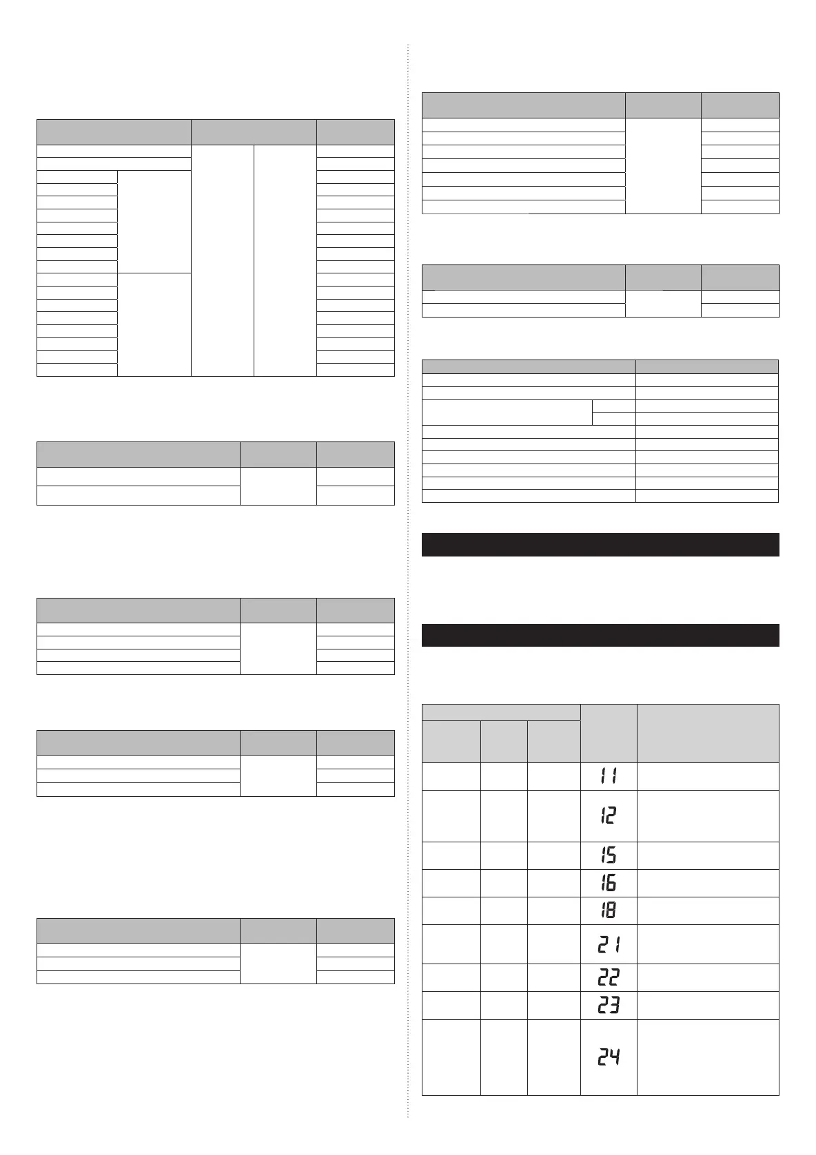
16. ERROR CODES
If you use a wireless remote controller, the lamp on the photo detector unit will output error
codes by way of blinking patterns. If you use a wired remote controller, error codes will ap-
pear on the remote control display. See the lamp blinking patterns and error codes in the
table. An error display is displayed only during operation.
Error display
Error code Description
OPERATION
lamp
(green)
TIMER
lamp
(orange)
ECONOMY
lamp
(green)
●
(1)
●
(1)
◊
Serial communication error
●
(1)
●
(2)
◊
• Wired remote controller
communication error
• Server room control
communication error
●
(1)
●
(5)
◊
Check run unfinished
●
(1)
●
(6)
◊
Peripheral unit transmission PCB
connection error
●
(1)
●
(8)
◊
External communication error
●
(2)
●
(1)
◊
Unit number or Refrigerant circuit
address setting error
[Simultaneous Multi]
●
(2)
●
(2)
◊
Indoor unit capacity error
●
(2)
●
(3)
◊
Combination error
●
(2)
●
(4)
◊
• Connection unit number error
(indoor slave unit)
[Simultaneous Multi]
• Connection unit number error
(indoor unit or branch unit)
[Flexible Multi]
9319357096_IM.indb 129319357096_IM.indb 12 2016/8/31 13:33:202016/8/31 13:33:20
 Loading...