En-9
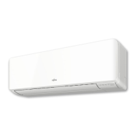
(10) Connect the end of the connection cable fully into the terminal block.
35 mm
25 mm
Earth (ground) wire
(11) Push the connection cable into the groove on the side of the electrical equipment lid.
Push into the groove.
(12) Fix the cables with the attached cable clamp with a screw.
Screw
Cable clamp
GOOD
PROHIBITED
Viewed from direction
A
GOOD
PROHIBITED
GOOD
PROHIBITED
Wireless LAN
adapter wiring
Connection cable
Arrange so that the connection cable is on
the left side, and the wireless LAN adapter
wiring on the right, and secure with the
cable clamp.
(13) Close the control box.
Please confi rm that the control box is closed completely.
Control box
Tab
(14) Attach the Wireless LAN adapter to the wall with 2 screws (Large).
For details, refer to the setting manual of wireless LAN control.
Install the wireless LAN adapter in the
direction as shown in the fi gure.
If the wireless LAN adapter is installed in
a wrong direction, water may get into the
adapter through the wire, causing failure.
Tapping screws
(Large)
GOOD PROHIBITED
Reverse direction On the fl oor
(15) Replace the front panel. (Refer to “9.3. Front panel removal and installation”.)
(16) Replace the dust box. (Refer to “9.2. Dust box removal and installation”.)
(17) Replace the wiring cover.
(18) Replace the intake grill. (Refer to “9.1. Intake grill removal and installation”.)
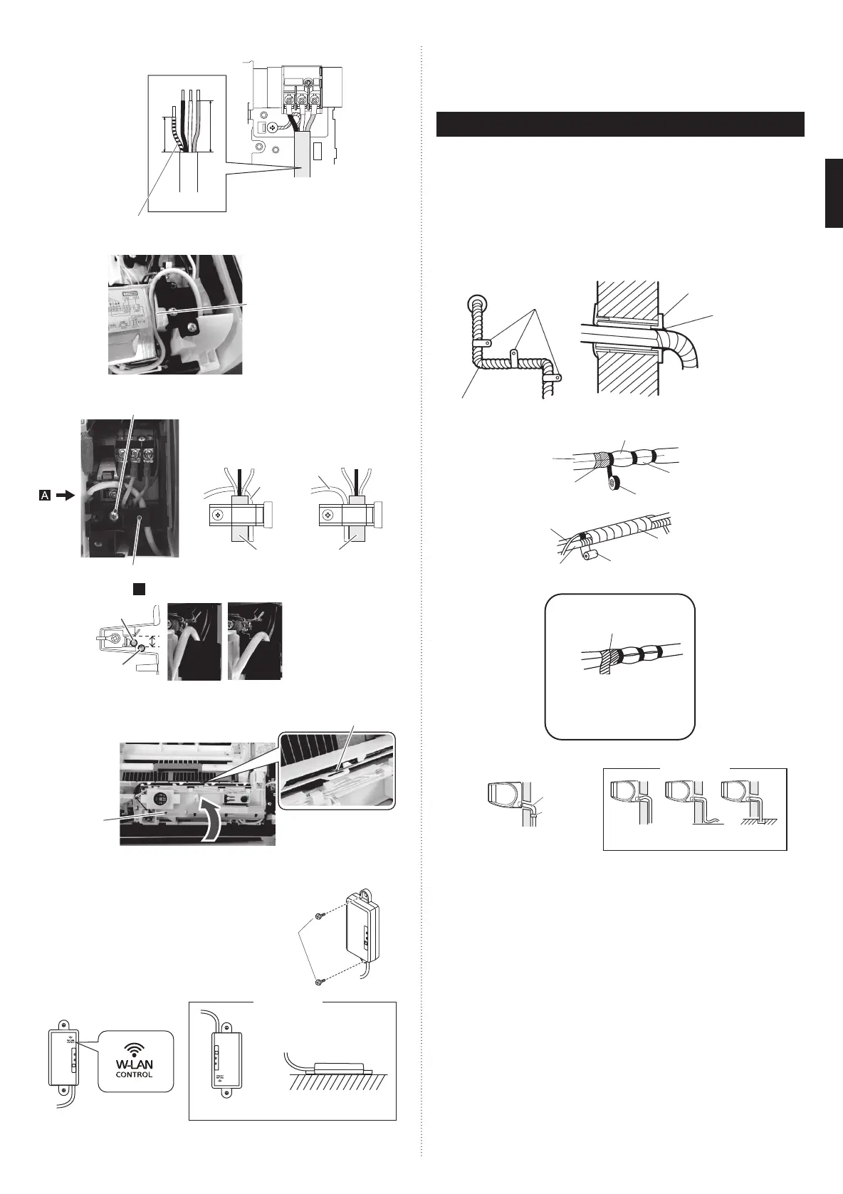
8. FINISHING
(1) Insulate between pipes.
• Insulate suction and discharge pipes separately.
• For rear, right, and bottom piping, overlap the connection pipe heat insulation and
indoor unit pipe heat insulation and bind them with vinyl tape so that there is no gap.
(2) Temporarily fasten the connection cable along the connection pipe with vinyl tape.
(Wrap to about 1/3 the width of the tape from the bottom of the pipe so that water
does not enter.)
(3) Fasten the connection pipe to the outside wall with a saddle, etc.
(4) Fill the gap between the outside wall pipe hole and the pipe with sealer so that rain
water and wind cannot blow in.
(5) Fasten the drain hose to the outside wall, etc.
*Locally purchased
Pipe
Saddle*
Outside wall cap*
Sealer putty*
(Outdoors)
Wall
Overlap the insulation
Vinyl tape
Wrap with cloth tape
Cloth tape
Drain hose
Pipe
Connection pipe
(heat insulation)
Indoor unit pipe
(heat insulation)
Bind the pipes together
so that there is no gap.
Drain hose insulation is used
when the diameter of gas pipe is
Ø12.70 or more.
Butt connection pipe (heat
insulation) against the indoor
unit pipe (heat insulation) and
wrap with drain hose insula-
tion so that there is no gap.
Check the following:
GOOD
Drain hose
Saddle
Lifted up Wave End in water
PROHIBITED
9319357096_IM.indb 99319357096_IM.indb 9 2016/8/31 13:33:172016/8/31 13:33:17
 Loading...