En-5
CAUTION
Do not install the unit in the following areas:
• Area with high salt content, such as at the seaside. It will deteriorate metal parts, caus-
ing the parts to fail or the unit to leak water.
• Area fi lled with mineral oil or containing a large amount of splashed oil or steam, such
as a kitchen. It will deteriorate plastic parts, causing the parts to fail or the unit to leak
water.
• Area where is close to heat sources.
• Area that generates substances that adversely affect the equipment, such as sulfuric
gas, chlorine gas, acid, or alkali. It will cause the copper pipes and brazed joints to cor-
rode, which can cause refrigerant leakage.
• Area that can cause combustible gas to leak, contains suspended carbon fi bers or
fl ammable dust, or volatile in fl ammables such as paint thinner or gasoline.
• If gas leaks and settles around the unit, it can cause a fi re.
• Area where animals may urinate on the unit or ammonia may be generated.
• Do not use the unit for special purposes, such as storing food, raising animals, grow-
ing plants, or preserving precision devices or art objects. It can degrade the quality of
the preserved or stored objects.
• Install the unit where drainage does not cause any trouble.
• Install the indoor unit, outdoor unit, power supply cable, transmission cable, and re-
mote control cable at least 1 m away from a television or radio receivers. The purpose
of this is to prevent TV reception interference or radio noise.
(Even if they are installed more than 1 m apart, you could still receive noise under
some signal conditions.)
• If children under 10 years old may approach the unit, take preventive measures so that
they cannot reach the unit.
• Install the indoor unit on the wall where the height from the fl oor is more than 1.8 m.
6. INSTALLATION WORK
WARNING
During transportation or relocation of the indoor unit, pipes shall be covered with the
wall hook bracket for protection. Do not move the appliance by holding the indoor unit
pipes.
(The stress applied to the pipe joints may cause the fl ammable gas to leak during
operation.)
CAUTION
• Do not hit or push the human sensor. This may lead to damage or malfunction.
• Do not touch the human sensor. Any scratches or dirt may lead to incorrect detection.
• Do not place large objects near the
human
sensor. Also keep heating units outside the
sensor’s detection area.
Detection range of the
human
sensor is as follows.
Vertical angle 90° (Side view)
90°
50°50°
7 m
7 m
Horizontal angle 100° (Top view)
You can change the orientation of the human sensor in accordance with the installation
position of the indoor unit. (Refer to “10. SETTING THE ORIENTATION OF THE HUMAN
SENSOR”.)
6.1. Installation dimensions
The flare connection
part should be installed
outdoors.
(Wall cap)
103 mm
or over**
74 mm or over*
Wall hook bracket
100 mm
or over**
100 mm
or over***
50 mm
or over
65 mm
95 mm
1.8 m or over
Remote
controller
Remote
controller
holder
Tapping screw
(small)
Lowest position of
the dual fan
Obstacles such
as curtains
* The distance between the wall hook bracket and the ceiling should be 74 mm or more.
** The side next to the sidewall must follow the size indicated in figure.
*** If the depth of the obstacle is more than 95mm, please keep the distance from the
indoor unit to the obstacle more than 100mm.
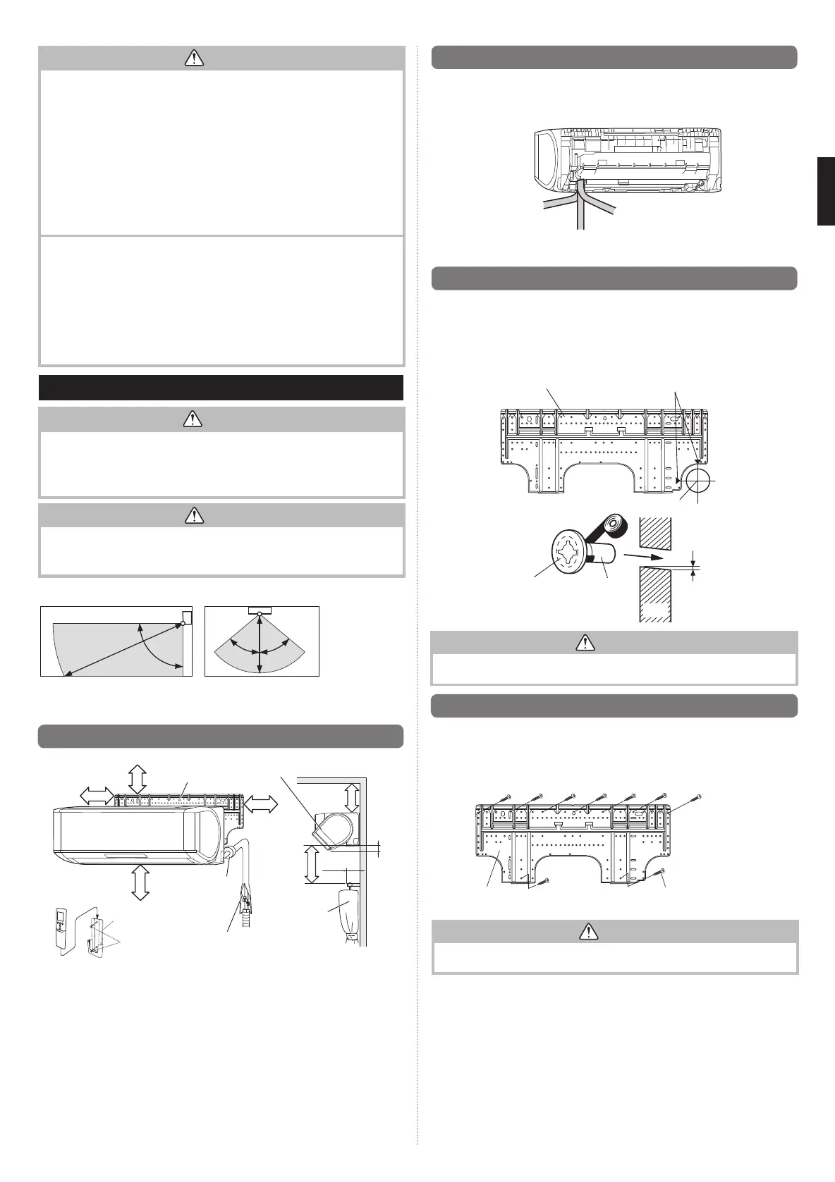
6.2. Indoor unit piping direction
The piping can be connected in the 3 directions in the fi gure. When the piping is con-
nected in direction (B) or (C), cut along the piping groove in the side of the front panel with
a hacksaw.
(B) Right
outlet
(A) Rear
outlet
(C) Bottom
outlet
(Rear)
6.3.
Cutting the hole in the wall for the connecting piping
(1) Cut a 65 mm diameter hole in the wall at the position shown in the following.
(2) Cut the hole so that the outside end is lower (5 to 10 mm) than the inside end.
(3) Always align the center of the wall hole. If misaligned, water leakage will occur.
(4)
Cut the wall pipe to match the wall thickness, stick it into the wall cap, fasten the cap with
vinyl tape, and stick the pipe through the hole.
(5) For left piping and right piping, cut the hole a little lower so that drain water will fl ow
freely.
Wall hook bracket
Centring marks
65 mm hole
Fasten with vinyl tape
5~10 mm
Wall pipe
(Field supply)
Wall cap
(Field supply)
(Inside)
(Outside)
Wall
WARNING
Always use the wall pipe. If the wall pipe is not used, the cable that is connected between
the indoor unit and the outdoor unit may touch metal, and cause an electric discharge.
6.4. Installing the wall hook bracket
(1) Install the wall hook bracket so that it is correctly positioned horizontally and vertically.
If the wall hook bracket is titled, water will drip to the fl oor.
(2)
Install the wall hook bracket so that it is strong enough to support the weight of the unit.
• Fasten the wall hook bracket to the wall with 9 or more screws through the holes near
the outer edge of the bracket.
• Check that there is no rattle at the wall hook bracket.
Wall hook bracket
Tapping screw (large)
(Accessory, 9 pcs)
CAUTION
Install the wall-hook bracket both horizontally and vertically aligned.
Misaligned installation may cause water leakage.
9319357096_IM.indb 59319357096_IM.indb 5 2016/8/31 13:33:142016/8/31 13:33:14
 Loading...