En-6
6.5.
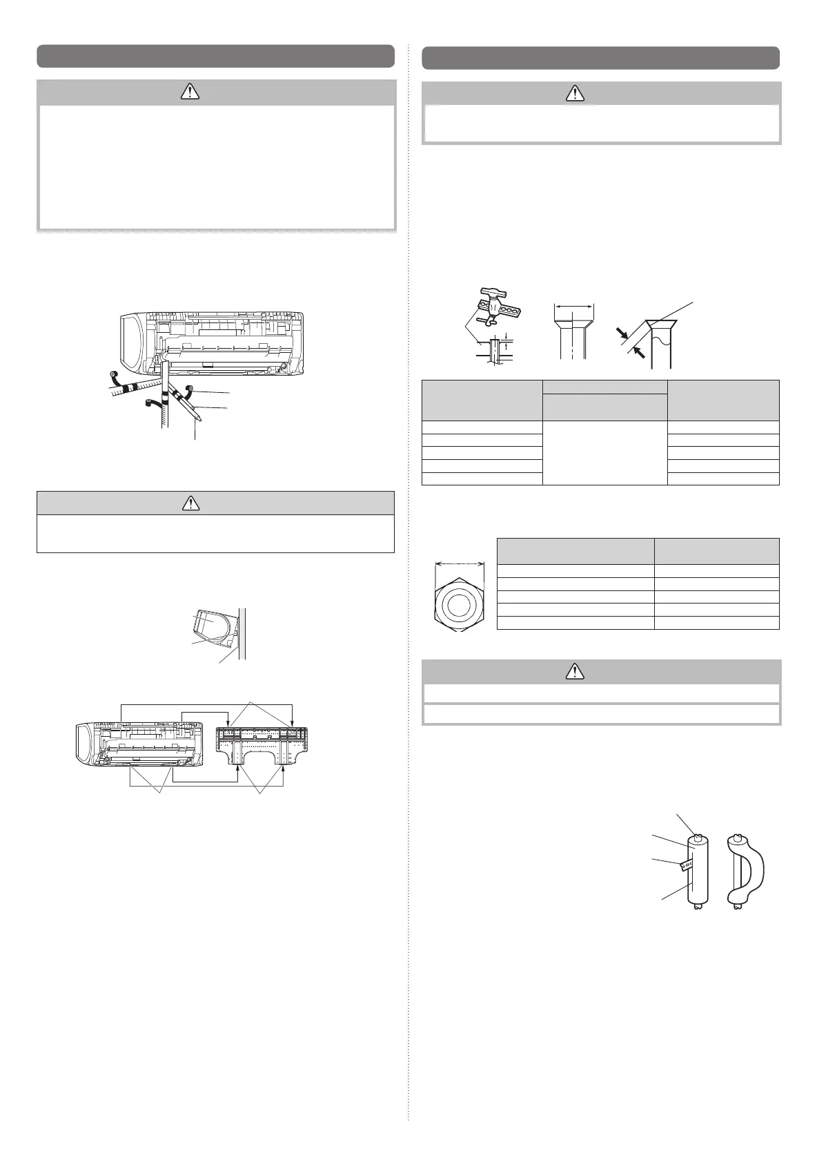
Forming the drain hose and pipe
CAUTION
• Insert drain hose and drain cap securely. Drain should slope down to avoid water leakage.
• When inserting the drain hose, no other material than water should be applied.
Application of other material than water will cause deterioration of the hose, and may
cause water leakage.
• After you remove a drain hose, be sure to attach the drain cap.
• When you secure the piping and drain hose with tape, arrange the drain hose so that
it is at the bottom of the piping.
• For drain hose piping in low temperature environment, you need to apply freeze
protection to prevent a frozen drain hose.
After cooling operation is performed in low temperature environment, (when outdoor
temperature under 0 °C,) water in the drain hose could be frozen. Frozen drain water
will block the water fl ow in the hose, and may cause water leakage at the indoor unit.
[Rear piping, Right piping, Bottom piping]
• Install the indoor unit piping in the direction of the wall hole and bind the drain hose
and pipe together with vinyl tape.
• Install the piping so that the drain hose is at the bottom.
• Wrap the pipes of the indoor unit that are visible from the outside with decorative tape.
Right piping
Bind with vinyl tape
Indoor unit drain hose
(bottom)
Pipe (top)
Rear piping
Bottom piping
CAUTION
Insert the drain hose and drain cap into the drain port, making sure that it comes
in contact with the back of the drain port, and then mount it. If the drain hose is not
connected properly, leaking will occur.
[Installing the indoor unit]
• Hang the indoor unit from the hooks at the top of the wall hook bracket.
• Insert the spacer, etc. between the indoor unit and the wall hook bracket and separate
the bottom of the indoor unit from the wall.
Indoor unit
Wall hook bracket
(Spacer)
Top hooks
Indoor
unit
(Fitting)
Bottom hooks
Wall hook
bracket
• After hooking the indoor unit to the top hook, hook the fi ttings of the indoor unit to the 2
bottom hooks while lowering the unit and pushing it against the wall.
6.6. Flare connection (Pipe connection)
CAUTION
Tighten the flare nuts with a torque wrench using the specified tightening method.
Otherwise, the fl are nuts could break after a prolonged period, causing refrigerant to leak
and generate hazardous gas if the refrigerant comes into contact with a fl ame.
6.6.1. Flaring
Use special pipe cutter and fl are tool designed for R410A or R32 pipework.
(1) Cut the connection pipe to the necessary length with a pipe cutter.
(2) Hold the pipe downward so that cuttings will not enter the pipe and remove any burrs.
(3) Insert the fl are nut (always use the fl are nut attached to the indoor unit(s) and outdoor
unit or branch box respectively) onto the pipe and perform the fl are processing with a
fl are tool. Use the special R410A or R32 fl are tool, or the conventional fl are tool. Leak-
age of refrigerant may result if other fl are nuts are used.
(4) Protect the pipes by pinching them or with tape to prevent dust, dirt, or water from
entering the pipes.
Die
A
Pipe
B
L
Check if [L] is flared uniformly
and is not cracked or scratched.
Pipe outside diameter
[mm (in.)]
Dimension A [mm]
Dimension B [mm]
Flare tool for R32,
clutch type
6.35 (1/4)
0 to 0.5
9.1
9.52 (3/8) 13.2
12.70 (1/2) 16.6
15.88 (5/8) 19.7
19.05 (3/4) 24.0
When using conventional fl are tools to fl are R32 pipes, the dimension A should be approx-
imately 0.5 mm more than indicated in the table (for fl aring with R32 fl are tools) to achieve
the specifi ed fl aring. Use a thickness gauge to measure the dimension A.
Width across
flats
Pipe outside diameter [mm (in.)]
Width across flats
of Flare nut [mm]
6.35 (1/4) 17
9.52 (3/8) 22
12.70 (1/2) 26
15.88 (5/8) 29
19.05 (3/4) 36
6.6.2. Bending pipes
CAUTION
To prevent breaking of the pipe, avoid sharp bends.
If the pipe is bent repeatedly at the same place, it will break.
• The pipes are shaped by your hands. Be careful not to collapse them.
• Bend R70 mm or more with a pipe bender.
• Do not bend the pipes in an angle more than 90°.
• When pipes are repeatedly bend or stretched, the material will harden, making it diffi cult
to bend or stretch them any more.
• Do not bend or stretch the pipes more than 3 times.
• When bending the pipe, do not bend it as
is. The pipe will be collapsed. In this case,
cut the insulating pipe with a sharp cutter
as shown on the right, and bend it after
exposing the pipe. After bending the pipe
as you want, be sure to put the heat insu-
lating pipe back on the pipe, and secure it
with tape.
Pipe
Insulating
Pipe
Cutter
Cut line
9319357096_IM.indb 69319357096_IM.indb 6 2016/8/31 13:33:152016/8/31 13:33:15
 Loading...