01-09
Check Item Check contents Judgement Present Status
Ref. circuit name _______________________, Ref. address ________(00
99)
Power
Source
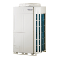
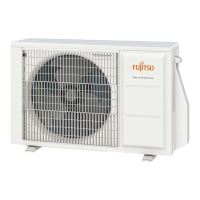
Outdoor Unit
Actual Power Supply (V)
Between R-S / S-T / T-R
< 3, 4Wire + ground, 50Hz >
AC (380 - 415V)
10%
Incoming volta ge per breaker
Master (V): R-S:_____ / S-T:____ / T- R:____
Slave -1 (V): R-S:_____ / S-T:____ / T-R:____
Slave -2 (V): R-S:_____ / S-T:____ / T-R:____
Indoor Unit
Actual Power Supply (V)
< 1, 2Wire + ground, 50Hz >
Incoming volta ge per breaker
Breaker-1 (V): _______
Breaker -2 (V): _______
Breaker -3 (V): _______
_______
Check Contents Judgement Present Status
Ref. circuit name ________________________, Ref. address ________(00
99)
For each
refrigerant
system
Outdoor unit Check PCB- Lighting status
Ma ster
LED101 (green light)
Judgment : must be ON
Yes / No
Note : LED102 (Red) must not be flash & must not be ON
7-SEG LED
Judgment : ‘Sn’ displayed
Yes / No
LED101: Yes No
7-SEG :
Yes No
Slave -1
LED101: Yes No
7-SEG :
Yes No
Slave -2
LED101: Yes No
7-SEG :
Yes No
Indoor unit Check LED & RC display status
IU address _______
IU address _______
IU address _______
IU address _______
IU address _______
IU address _______
IU address _______
IU address _______
IU address _______
IU address _______
IU address _______
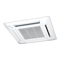
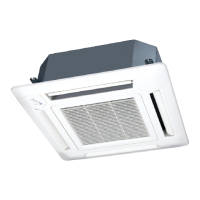
Indoor Unit
For Wall mounted, Universal, Celling & Small Cassette
Check IU operation LED & timer LED condition
Judgment : must be flashing alterna tely
Yes / No
For Large Cassette and Duct type IU
Check Wired RC (3-wire) display screen
Judgment : Clock display “AM 12:00” will a ppear
Yes / No
Check Wired RC (2-wire) display screen
Judgment : Langua ge selection screen will appear
Yes / No
Yes No
Yes No
Yes No
Yes No
Yes No
Yes No
Yes No
Yes No
Yes No
Yes No
Yes No
Yes No
AC (220 - 240V) 10%
Overview of system operation check procedure
Step-1: Connect Service Tool PC to the VRF V-III system.
Do scaning of refrigerant system which should be commissioned.
Step-2: Compare the number of installed units (OU and IU) with the System List data obtained from the Service Tool.
Step-3: Operate all Indoor Units under Test Mode Cooling (Select Test mode either cool or heat based on ambient temperature.).
Step-3-1: During operation, check the IU thermistor value
Step-3-2: After 1-hour operation, check the Refrigerant System
Step-4: After 1-hour Test run operation (excluding special operation),
Step-4-1: Switching the operation mode of IU from cool to heat.
- Check the IU thermistor value
Step-4-2: When all IUs run under heating, continue operation minimum 15min. And check the Refrigerant system
1-3-2 Error indication check sheet
1-3 Check Items After Power ON
1-3-1 Power source check sheet
 Loading...