Do you have a question about the Fujitsu ETERNUS DX60 and is the answer not in the manual?
Describes safety considerations for the ETERNUS DX60/DX80/DX90. Follow handling instructions and cautionary notes for safety.
Explains how to use the manual, emphasizing safety precautions before connecting the device for proper operation.
Outlines the structure of the manual, detailing the content of each chapter from Overview to Appendices.
Explains the various warning symbols used in the manual, their levels of caution, and their specific meanings.
Details the warning and manufacturer labels found on the controller enclosure, including their locations.
Describes the warning and manufacturer labels located on the drive enclosure, shown in an example diagram.
Illustrates the placement of the manufacturer's label on the 1U AC Outlet Box, showing its location.
Shows the location of the manufacturer's label on the 2U AC Outlet Box for identification purposes.
Details the special features of the ETERNUS DX60/DX80/DX90, covering compact design, energy savings, and eco-mode functions.
Discusses important items to consider before configuring the ETERNUS DX60/DX80/DX90 systems.
Describes supported RAID levels, their mechanisms, selection criteria, and RAID group configuration.
Explains how to set up RAID groups using the same or mixed RAID levels and defines volumes as basic RAID units.
Describes system disks, their assignment for system area, and their installation in controller enclosure slots, with a warning not to remove them.
Explains the use of hot spares for RAID group failures, covering Global and Dedicated hot spares and their registration.
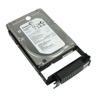
Details the three types of drives (SAS, Nearline SAS, SSDs) and their suitable usage cases, including 2.5" vs 3.5" differences.
Describes the three host interface types supported: Fibre Channel, iSCSI, and SAS, detailing their characteristics and typical uses.
Introduces the main functions of the ETERNUS DX60/DX80/DX90 storage system.
Explains the Rebuild/Copyback function which restores disk status to normal after a RAID group failure by using hot spares.
Describes Advanced Copy functions for high-speed data copying without server resources, including uses like snapshots and fast data copies.
Explains RAID migration for transferring volumes between RAID groups or changing RAID levels while ensuring data integrity.
Describes Logical Device Expansion (RAID Group Expansion) for dynamically extending RAID group capacity by adding disks without creating new groups.
Explains LUN concatenation for adding new area to a volume, expanding capacity, and reusing free space in RAID groups.
Details security functions like LUN mapping and Host Affinity to control server access to volumes, enhancing security.
Explains Eco-mode for reducing power consumption by stopping disk spindle rotation during specified periods or inactivity.
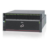
Describes the 3.5" type controller enclosure, detailing its front view components like LEDs and switches.
Details the front view of the 3.5" type controller enclosure with the front cover, explaining the function of each LED and the power switch.
Identifies the rear view components of the 3.5" type controller enclosure for single and dual controller models.
Details the controller module for ETERNUS DX60/DX80 Fibre Channel models, explaining its ports, LEDs, and SCU status.
Describes the controller module for the ETERNUS DX90 Fibre Channel model, including ports, LEDs, and SCU status.
Explains the controller module for ETERNUS DX60/DX80 iSCSI models, detailing ports, LEDs, and SCU status.
Details the controller module for ETERNUS DX60/DX80 SAS models, explaining its ports, LEDs, SCU status, and the importance of the SCU.
Describes the power supply unit for the 3.5" type controller enclosure, including its status LED and important connection notes.
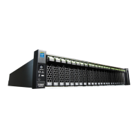
Describes the 2.5" type controller enclosure, covering its front view with flange cover and associated LEDs.
Identifies the rear view components of the 2.5" type controller enclosure for single and dual controller models.
Details the controller module for ETERNUS DX60/DX80 Fibre Channel type, explaining ports, LEDs, and SCU status.
Describes the controller module for the ETERNUS DX90 Fibre Channel model, including ports, LEDs, and SCU status.
Details the power supply unit for the 2.5" type controller enclosure, including its status LED and important connection notes.
Describes the 3.5" type drive enclosure, covering its front view with front cover and associated LEDs.
Identifies the rear view components of the 3.5" type drive enclosure for single and dual expander models.
Describes the expander for the 3.5" type drive enclosure, detailing its ports, LEDs, and identify function.
Details the power supply unit for the 3.5" type drive enclosure, including its status LED and internal cooling fans.
Describes the 2.5" type drive enclosure, covering its front view with flange cover and associated LEDs.
Identifies the rear view components of the 2.5" type drive enclosure for single and dual expander models.
Describes the expander for the 2.5" type drive enclosure, detailing its ports, LEDs, and identify function.
Details the power supply unit for the 2.5" type drive enclosure, including its status LED and internal cooling fans.
Introduces the AC outlet box and mentions there are two sizes: 1U and 2U.
Details the specifications for the 1U AC outlet box, including power, inlet/outlet connections, dimensions, and weight.
Provides specifications for the 2U AC outlet box, including power, inlet/outlet connections, dimensions, and weight.
Explains the procedure for turning on the ETERNUS DX60/DX80/DX90, including initial power-on diagnostics and readiness checks.
Explains the procedure for turning off the ETERNUS DX60/DX80/DX90, emphasizing the importance of data writing to disk and safe power-off.
Details the procedure for attaching and removing the front cover of the 3.5" controller/drive enclosures, with caution about the power switch.
Explains how to attach and remove the flange cover for 2.5" controller/drive enclosures, with a caution about the power switch.
Describes how to enable AC automatic linkage mode by turning the AUTO POWER switch ON, which allows automatic turn-on after power recovery.
Explains the importance of wearing the wrist strap to discharge static electricity during operations like installing components or connecting cables.
Outlines the necessary preparation steps, including package contents check, manual preparation, and installation/connection checks.
Describes the procedure for installing the ETERNUS DX60/DX80/DX90 in a rack, including rack mount kit attachment.
Details the various cables that need to be connected, such as LAN, Fibre Channel, miniSAS, and power cords.
Explains the startup procedure, including connecting the PC via LAN and turning on the ETERNUS DX60/DX80/DX90.
Guides through the basic setup using GUI, covering initial setup, configuration wizard, and hot spare registration.
Covers additional settings required for Advanced Copy, monitoring setup, and server connection setup.
Refers to Chapter 9 for details on operating and maintaining the ETERNUS DX60/DX80/DX90.
Covers preparations for installation, including checking the placement area, installation conditions, and air conditioning requirements.
Details how to check the required type and number of wall outlets, and lists wall outlet connectors and cable lengths.
Explains how to determine the number of power outlets needed based on the count of drive enclosures and AC outlet boxes, with tables for connected and not connected scenarios.
Describes the procedure for installing the ETERNUS DX60/DX80/DX90 in a rack, including safety precautions and installation conditions for different rack brands.
Details the procedure for installing the controller enclosure in a rack, including checking for missing parts and the order of installation.
Describes the procedure for installing a drive enclosure in a rack, with a caution regarding improper installation.
Describes how to install the 1U AC outlet box in a rack, with a caution that it cannot be connected to other devices.
Describes how to install the 2U AC outlet box in a rack, with a caution that it cannot be connected to other devices.
Lists required preparations before connecting cables, including networking equipment, power checks, and related manuals.
Explains the necessity of LAN connection for settings, management via GUI/CLI, and remote support, specifying port usage.
Details connecting the ETERNUS DX60/DX80/DX90 and server/Fibre Channel switch using Fibre Channel cables, emphasizing cable handling.
Explains connecting ETERNUS DX60/DX80 with servers or hubs using LAN cables for iSCSI, recommending a separate LAN and 1Gbit/s support.
Details connecting the ETERNUS DX60/DX80 with servers using miniSAS cables for SAS interface, emphasizing proper cable handling.
Explains connecting Drive Enclosures to the Controller Enclosure using miniSAS cables, including cable types and quantities.
Explains how to connect power cords to the ETERNUS DX60/DX80/DX90, including important safety warnings regarding handling and usage.
Details connecting power cords directly to the ETERNUS DX60/DX80/DX90 when no AC outlet boxes are installed, emphasizing PSU connections.
Explains connecting power cords from the 1U AC outlet box to the ETERNUS DX60/DX80/DX90 power supply units.
Details connecting power cords from the 2U AC outlet box to the ETERNUS DX60/DX80/DX90 power supply units.
Outlines preparations for setting up the ETERNUS DX60/DX80/DX90, including related manuals, network settings, and PC preparation.
Guides through the basic setup of the ETERNUS DX60/DX80/DX90, starting with turning the device on and checking PC connectivity.
Describes the initial setup process using GUI, including starting the web browser and entering the device's IP address.
Explains how to set the date and time for the ETERNUS DX60/DX80/DX90's internal clock.
Guides on setting the system name, which is used for network management and displayed in the GUI.
Details the process of changing the initial account password for enhanced security.
Explains how to change the Fibre Channel port mode (CA or RA) on ETERNUS DX90, with important notes on data deletion.
Guides on setting connecting information for ports, noting that screens vary by model and mentioning Host Affinity settings.
Details setting Fibre Channel port parameters, including port selection and necessary items in "Port Settings".
Explains setting iSCSI port parameters, including iSCSI name, IP address, and server details.
Details setting SAS port parameters, including SAS address, server name, and host response.
Guides on setting up the network environment for communication, including IP address, subnet mask, and default gateway.
Explains how to perform device operation settings using the Configuration Wizard, covering RAID group creation, volume definition, and host setup.
Guides on starting the Configuration Wizard by clicking the button on the GUI's [Easy Setup] tab.
Details creating or selecting a RAID group for volume creation, with important notes on factory defaults and disk types.
Explains creating a volume within a RAID group, with notes on deleting factory settings if custom configurations are desired.
Guides on setting up the host server connection, including registering Fibre Channel card WWN or iSCSI/SAS details.
Explains creating an affinity group when using the Host Affinity function, linking volumes to servers.
Details configuring LUN mapping to set volumes recognized by the server, explaining steps for when Host Affinity is used.
Explains how to correspond volume numbers to LUNs for ports when Host Affinity is not used.
Guides on registering hot spares for disk failure, covering Global and Dedicated hot spares and capacity requirements.
Explains how to activate Advanced Copy functions by registering licenses for ETERNUS SF Snap/Clone, AdvancedCopy Manager, or Advanced Copy Feature.
Details obtaining the Advanced Copy license key, including preparing license documents and checking existing registrations.
Explains how to register the obtained license key using the GUI to activate Advanced Copy functions.
Guides on verifying license registration by checking the Advanced Copy Status screen in the GUI.
Refers to the Web GUI or CLI User Guides for Advanced Copy function settings and operations.
Explains how to perform monitoring setup for event notification via E-Mail, SNMP trap, host sense, and REMCS.
Details setting up event notification methods and levels when problems occur, including E-mail and SNMP trap configurations.
Explains how to set up E-mail notifications for errors, including specifying the destination e-mail address and mail server settings.
Explains setting up SNMP Trap notifications using ServerView for monitoring events when connected to a PRIMERGY server.
Explains how to set up remote support service to report ETERNUS DX60/DX80/DX90 problems to a remote support center.
Guides on performing settings to connect to the server, install drivers, and check connections.
Explains how to check the system status using GUI or CLI, including parts, RAID group, and volume status.
Describes how to check the status of ETERNUS DX60/DX80/DX90 components via the GUI, identifying normal status and abnormalities.
Explains how to check the status of registered RAID groups on the GUI to verify correct configuration.
Guides on checking the status of registered volumes on the GUI to ensure they are set correctly.
Explains how to install optional disks in the ETERNUS DX60/DX80/DX90, covering disk handling instructions and installable disk types.
This section describes how to install optional disks in the ETERNUS DX60/DX80/DX90.
Provides instructions for handling disks, including precautions regarding condensation, static electricity, and physical shocks.
Explains the positions where disks can be installed in the front of controller and drive enclosures, showing diagrams for 3.5" and 2.5" disks.
Describes the procedure for installing additional disks, including warnings against unauthorized disks and system disk removal.
Provides a procedure for installing 3.5" disks, including checking for missing items, verifying component status, and wearing a wrist strap.
Provides a procedure for installing 2.5" disks, including checking for missing items, verifying component status, and wearing a wrist strap.
Explains how to install a drive enclosure in the ETERNUS DX60/DX80/DX90, covering handling instructions and precautions.
Provides handling instructions for drive enclosures, including precautions for condensation, static electricity, and physical shocks.
Lists installable drive enclosures and notes that 2.5" disk models cannot be installed in the ETERNUS DX60 2.5" disk model.
Describes the procedure for installing a drive enclosure in a rack, including safety precautions and order of installation.
Describes the procedure for installing an additional drive enclosure, including initial checks, wearing a wrist strap, and starting the GUI wizard.
Guides on connecting the miniSAS cable between the controller and drive enclosures.
Explains connecting the power cord to turn on the drive enclosure.
Explains how to check the system status regularly using LEDs, GUI, or CLI, and mentions monitoring setup for notifications.
Emphasizes the importance of regularly backing up important data to a tape drive or similar device to prevent data loss in case of system failure.
Explains the maintenance service for the ETERNUS DX60/DX80/DX90, including PC connection for maintenance and engineer information.
States the maintenance support period for the ETERNUS DX60/DX80/DX90 is 5 years from the date of purchase.
Details procedures for changing the configuration after system operation begins, such as replacing Fibre Channel, LAN, or SAS cards.
Explains how to replace a failed Fibre Channel card, including checking WWN/host affinity, server-side replacement, and adjusting settings.
Details how to replace a failed LAN card or iSCSI HBA, including turning off the server and confirming server access after settings.
Explains how to replace a failed SAS card, including checking SAS address/host affinity, server-side replacement, and confirming server access.
Provides guidance on troubleshooting unusual phenomena, system status checks, and recording information for maintenance engineers.
Lists common unusual phenomena and troubleshooting steps, including warnings for overheating or abnormal conditions.
Provides points to check if the system is turned off, covering power cord, AC outlet box switch, and power failure.
Lists checks for when the system refuses to turn on, including power cord, AC outlet box, and miniSAS cable connections.
Advises contacting a maintenance engineer if the READY LED does not turn on after 10 minutes of power-on.
Guides on checking GUI status and contacting a maintenance engineer if the FAULT LED is on.
Explains how to interpret the FAULT LED blinking status and check the Storage System Status screen for details.
Details steps to reset the network settings to factory defaults and set a new IP address if it is forgotten.
Provides points to check when the device is not accessible via the network, including LAN cable, network devices, and IP address settings.
Guides on setting up the network environment, enabling necessary network services like http, https, telnet, and SSH.
Advises checking the serial number if the license key cannot be registered, and contacting sales representatives for assistance.
Recommends contacting a maintenance engineer to determine the cause of server-displayed error messages.
Suggests using volume-adding functions like LUN concatenation and RAID migration to resolve capacity shortages.
Provides checks for slow I/O access, including ambient temperature, component status, path status, and load balancing.
Addresses issues where servers do not recognize disks, covering all servers and specific servers, and referring to replacement procedures.
Provides a form for recording trouble details, including system identification, number of components, UPS usage, and LED status.
This section explains the specifications of the ETERNUS DX60/DX80/DX90 devices.
Details the specifications for ETERNUS DX60 models, covering disk types, RAID levels, capacity, interfaces, and controllers.
Details the specifications for ETERNUS DX80 models, covering disk types, RAID levels, capacity, interfaces, and controllers.
Provides the specifications for ETERNUS DX90 models, including disk types, RAID levels, capacity, host interfaces, and controllers.
This section explains the specifications of the ETERNUS DX60/DX80/DX90 optional products.
Explains the specifications for various optional disks, including SAS and Nearline SAS disks in 3.5" and 2.5" form factors.
Explains the specifications for optional drive enclosures, covering 3.5" and 2.5" type models.
Introduces AC Outlet Box specifications.
Details the specifications for the 1U AC outlet box, including power, inlet/outlet connections, dimensions, and weight.
Provides specifications for the 2U AC outlet box, including power, inlet/outlet connections, dimensions, and weight.
Lists specifications for Expansion Controllers for both 3.5" and 2.5" disk models, including model name, dimensions, and weight.
Lists specifications for Expansion Controllers for the 3.5" disk model.
Lists specifications for Expansion Controllers for the 2.5" disk model.
Details specifications for Expansion Expanders for 3.5" and 2.5" disk models, including dimensions, weight, and miniSAS cable details.
Provides specifications for the Extension Cable Kit, including model name, connection type, and length.
Lists events detected by ServerView, their severity, specific TRAP numbers, and meanings, with default settings for notification.
Mentions the open sources used by the SMI-S interface: OpenPegasus and OpenSSL.
Provides the copyright and license information for OpenPegasus, including its terms of use and conditions.
Explains that both OpenSSL and SSLeay licenses apply to OpenSSL, providing license information and usage conditions.