54 Operating Manual TX2550 M4
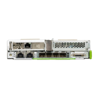
Figure 5: Connector panel
* When using an OCP module, the standard PCIe x16 slot is not usable.
The corresponding indicators are explained in section "Server rear" on page 67.
I Some of the devices connected require special software (e.g. drivers)
(see documentation for the connected device).
I The LAN connectors on the OCP modules are numbered in ascending
order from right to left beginning with “0”. The rightmost connector (LAN
0) is the shared LAN connector respectively.
Ê Connect the devices to the server.
1 Serial connector (optional)* 5 2 USB connectors (USB 3.0)
2 Shared LAN connector 6 Video connector (VGA)
3 LAN connector 7 Management LAN connector (for
iRMC S5 server management
function)
4 2 USB connectors (USB 3.0) 8* Dedicated slot for OCP modules

 Loading...