- (OP005 - 08) -
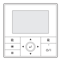
WIRED REMOTE
CONTROLLER
WIRED REMOTE
CONTROLLER
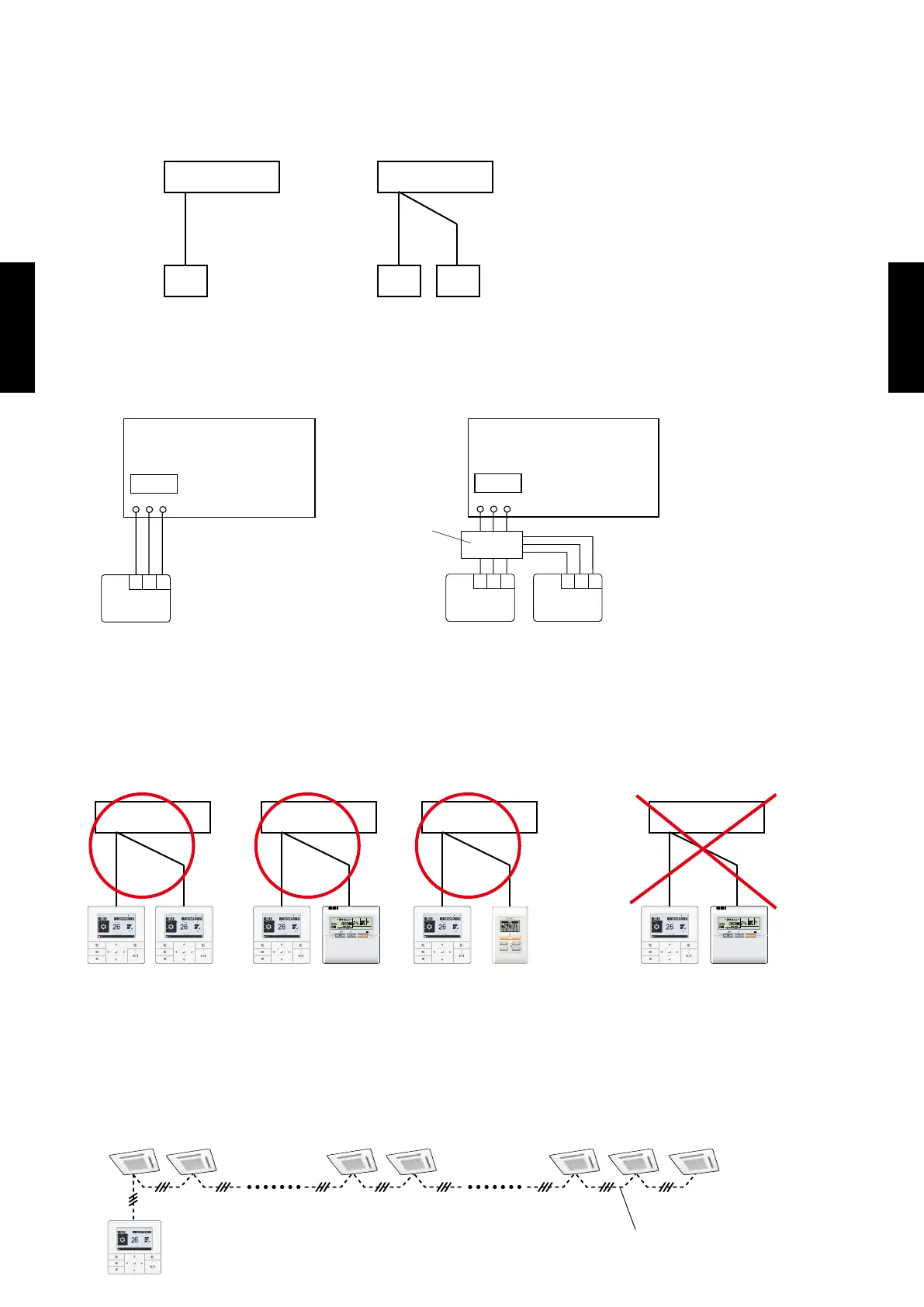
WIRING DESIGN5.
SYSTEM DIAGRAM
1 remote controller
z
z
2 remote controllers
Indoor unit Indoor unit
Remote controller Remote controllers
A , B , C : Remote controller cable.
ELECTRICAL WIRING
1 remote controller
z
z
2 remote controllers
REMOTE
CONTROLLER
1 2 3
1 2 3
1 2 3
1 2 3 1 2 3
REMOTE
CONTROLLER
Remote controller Remote controllers
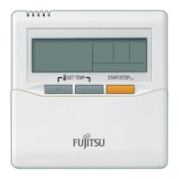
1. 12V (Red)
2. Signal (White)
3. COM (Black)
Junction box
(eld supply)
CONTROLLER COMBINATION
As for the combined usage of the controller, refer to following gures.
Good
z
z
Prohibited
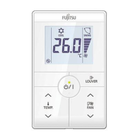
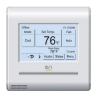
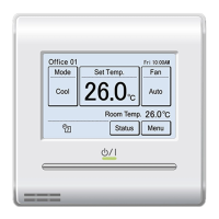
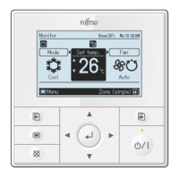
UTY-RVNM
UTY-RVNYN
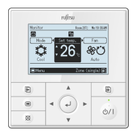
UTY-RNNM
UTY-RNNYN
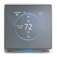
UTY-RNBYU
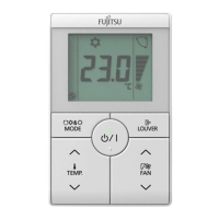
UTB-UD
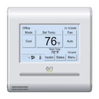
UTY-RVNM
UTY-RVNYN
UTY-RSNM
UTY-RVNM
UTY-RVNYN
UTB-UB
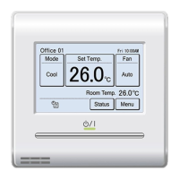
UTY-RVNM
UTY-RVNYN
UTY-RVNM
UTY-RVNYN
SET TEMP.
START/STOP
SET TEMP.
START/STOP
Indoor unit Indoor unit Indoor unit Indoor unit
REMOTE CONTROLLER GROUP CONTROL
1 or 2-remote controllers can simultaneously control up to 16 indoor units.
Connection examples
z
 Loading...