(i) Centralcontroller♦:
A central remote controller can control multiple R.C.
Groups. There is a system controller, Touch panel con-
troller, and a central remote controller.
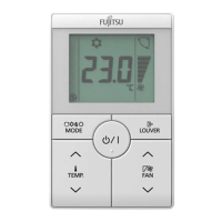
(j) Standardremotecontroller:
A standard remote controller can control 1 R.C. Group
only. This unit corresponds to this. This unit cannot be
used together with a 3-wire wired remote controller. A
wireless remote controller can be used together with
this unit.
Address related terms
(k) Indoorunitaddress♦:
This is an ID individually assigned to each indoor unit.
(l) Remotecontrolleraddress:
This is an ID individually assigned separately from the
indoor unit address to indoor units which form an R.C.
Group.
1-2-2 Passwordconguration
Thisunitcansetthefollowing2kindsofpasswords:
(a) Admin password
This is a password for administrator. Password is re-
quested by the setting which requires management. For
a description of password setting and change, refer to [5
Setting]→[5-2InitialSetting]→[5-2-2AdminPassword].
(b) Installer password
This password is requested for important settings at
installation.
NOTE
If you forget your password, contact your local dealer.
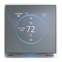
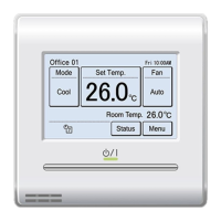
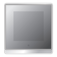
1-3 Name of parts
(a)
(b)
(c)
(d)
(a) Touch screen
It can be operated by tapping or swiping.
NOTE
Operate with your finger or stylus pen (not included). Do
not touch the screen with a hard or sharp object as it may
cause a malfunction.
(b) Ambient light sensor
Detects the brightness around the controller.
(c) Operation lamp
It is lights up in a color according to the operation mode
while indoor unit operating. Light goes out while stopped.
Blinks when an error is detected.
Lighting
color
Blue Green Red Purple White
Operation
mode
Cool Dry
Heat or
10°C
(50°F)
heat
Auto or
Custom
auto
Fan
NOTE
The operation lamp can be turned off at all times. For
details, refer to “5-3-8 Operation Lamp”.
(d) Room temperature sensor (inside)
Detects the temperature around the controller.
1-4 Before operation or setting
1-4-1 Wake the controller
If the standby screen is displayed, tap the screen to display
the temperature setting screen (home screen).
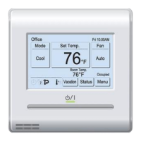
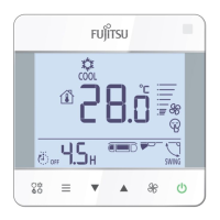
1-4-2 Standby mode screen
The standby mode screen varies depending on the settings.
■
Example of standby mode screen
(a)
(b)
(a) Remote controller group name
Appears when a name is set. Refer to “5-2-1 RC (Remote
Controller) Group Name”.
(b) Room temperature (Celsius or Fahrenheit)
NOTES
• If there is no operation for a certain period of time, the
controller display will disappear or the standby mode
screen will be displayed.
• The standby mode screen is displayed when “5-3-7-3
Time after lighting” is set to “Dimming”.
• The time until the standby mode can be set to 30 sec-
onds, 60 seconds, 90 seconds, or 120 seconds. For
details,referto“5-3-7-4AutomaticOTime”.
En-4
 Loading...