- (OU01 - 16) -
Outdoor unit / Single phase
OUTDOOR UNIT
WO
G112-140LCTA
OUTDOOR UNIT
WO
G112-140LCTA
Peak cut mode
z
Operation that suppressed the current value can be performed by means of the following on-site •
work. The outdoor unit is set to the Peak cut mode by applying the contact input of a commercial
ON/OFF switch to a connector on the outdoor control PC board.
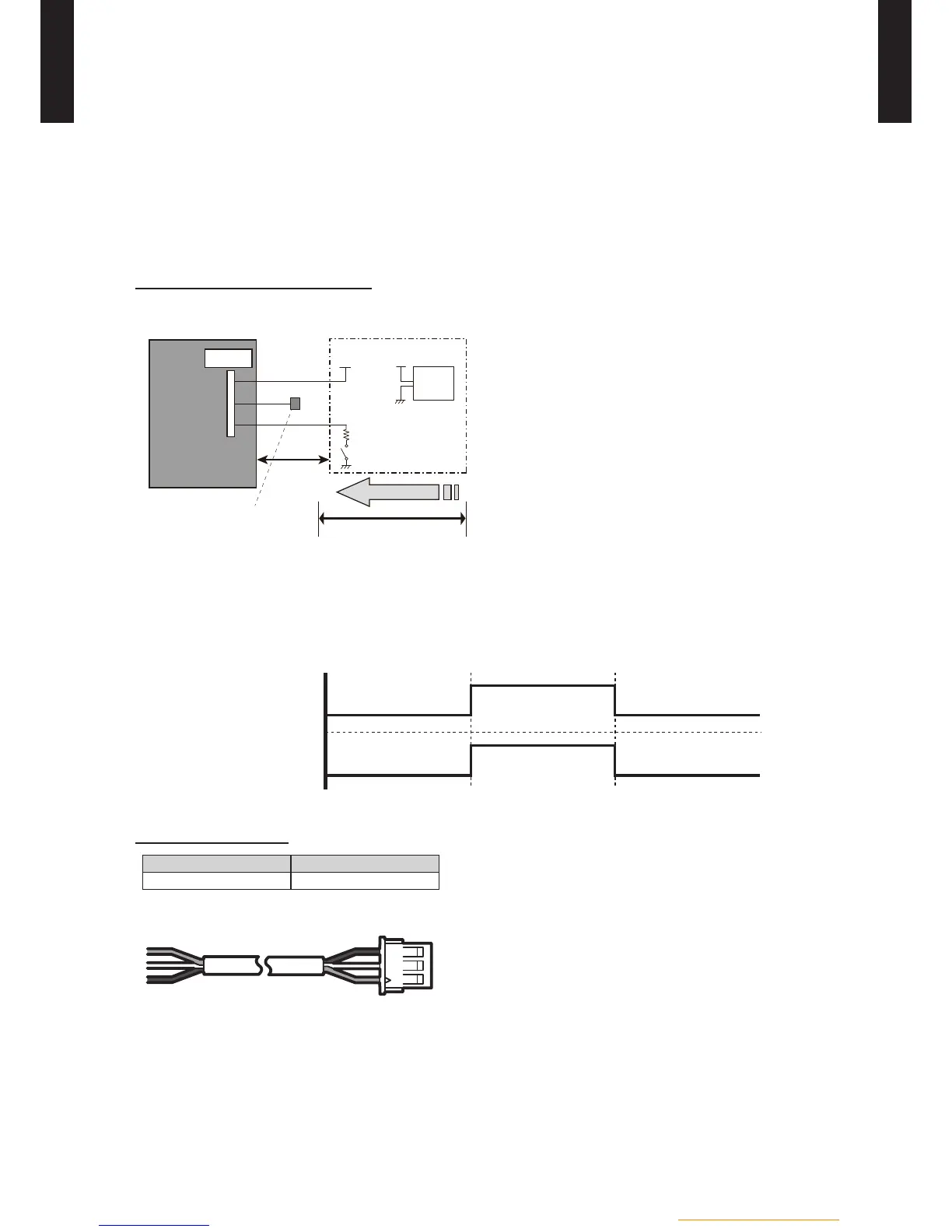
Circuit diagram example
Use the following parts and construct a circuit like that shown above. •
Input signal∙∙∙ON: Peak cut mode/OFF: Normal operation
•
*Set the "Peak cut mode" type by "Push switch" on the outdoor control PC board.
Parts (Optional)
Parts name Model name
External connect kit UTY-XWZXZ2
Wire (External input) : Red / White / Black
1) Power supply
●Voltage (Chart sign=Vcc) : DC 5V to 24V
●The current capacity : About 100mA
2) Switch (Chart sign=SW)
● Toggle switch or Rocker switch, etc : Switch which maintains the
states.
● Prepare switches which are enough capable for DC 10mA
current or more
3) Resistance (Chart sign=R)
●Adjust the resistance for current to about DC 10mA
(Example)
●In case of Vcc=DC 5V : Rated resistance value 470Ω 1/4W
●In case of Vcc=DC 12V : Rated resistance value 1kΩ 1/4W
●In case of Vcc=DC 24V : Rated resistance value 2.2kΩ 1/4W
 Loading...