Fig 6-2 Rel ationship b etween environme nt a nd C arrier fre quency
Relationship bet ween Model and Carrier frequency
This f unc tionis m ainly used t oimprove the m otor operating noi seand i nvert er int erfe rence to external.
The a dvantagesof using high carrier frequency: re latively ideal current w ave shape, less harmonic
current waveand low motor nois e;
T he di sa d van tag es of us in g hig h c ar rie r fr e quenc y : in creased sw it ch loss and inv ert er tempera t ure r ise s,
affectinginvert er output c ap acit y so that itshould be operated at derating underhi ghc arrier frequency
conditions; in themean time, inverterleakage current and it selectromagneticinterf erence to ext ern al are
increased.
The situat ionsof usingl owcarrier frequency is on the contrary. Too low carrier frequency canc ause
operationunstable,torque reduceda ndeven oscillation atlow f requ enc y.
When inve rte r i sfactory released, its carrierfrequenc y has been set properly. Generally the u ser does
notneedtomodifythisparameter.
Carr ier
frequency
E l ect ronmagnet ic
noise
Ca co ph ony,
Leakage current
Heat radiation
1KHz
10KHz
15KHz
large
smal l
large
small
large
small
C arrier f re quency
Model
Fac tory
setting
(KHz)
B:0.4kW
~11KW
P:0.75
kW~15KW
15 1 8
B:15kW~55KW
P:18.5kW~75KW
814
B:75kW
~300KW
P:90kW
~315KW
6
1
2
Min carrier
frequency
(KHz)
Max carr ier
frequency
(KHz)
F0.11
Carr ier f requ enc y set ti ng
1.0 15 .0kHz
~
Set by
model
Fu nction
Code
Name
Settin g Range
Default
Value
Chapter 6 Parameter D escripti on
DZB Series
-38-
0: Operating at defaultdirection.W hen the inverter is powe rconnected, it operatesat the actual direction.
1: Operating at reverse direction. By meansof changi ngthe f unction code, the motor rota ti ngdi rectioncan
be changed wi thout changing any other parameters,which is e quiva lentto ch ange the mot or rotating
dire ct ion by exchanging any two of mot or cables(U ,V, W).
2: Forbidi nverse operating. Forbiddinginverterinver seoperation is suitable to specifica pplicat ion that
inve rseoperating is forbidden.
Note: Afte r th e pa rameters are i ni tia lized, the m otor op era ti ng dir ec tion c a n be r es tore d t o be it s
origina l s ta te . Be c au tio n t o use it in the c a se that chan gin g m otor ro ta tin g di re ct ion is forbidden afte r
the sy ste m commissi oni ng is c o mp lete d.
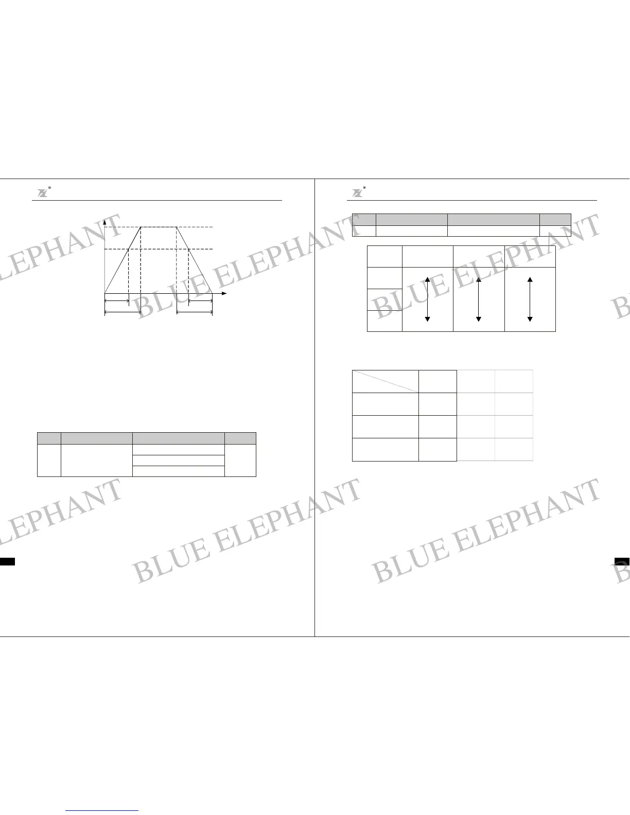
Fig 6-1 Acceleration a nd Decelerationtime diagram
Outputfrequency f
f
max
f
set
actu al acce.
time
set a cce.t ime
actual dece.
time
set dece.time
Time t
Whenthe set frequencyis equalto themaximum frequency,the actualAcceleration/Deceleration time
are equa l to the s et Acc el era ti on /De cele ra tion ti m e .
Whenthe set frequency is less than themaximum frequency, the actual Acceler ation/Deceleration tim e
are less than t he setAcce le ration/ Dec elera tiontime.
Actual A cceler ation /Decelera tiontime= set Accel eration/Deceleration t ime (set frequency/max.
frequency)
DZB200&300 ser ies inverterhas 2 groupsof Acceleratio n/Deceleration time.
1st group: F0.08, F0.09;
2ndgroup: F4.00, F4. 01;
The Accel er ation /Decelerationtimecanbe chosenthrough mult if unction digitalinput te rmina l (F2 Group).
×
F0.10
Opera tion d irection
sele ct ion
0 Operating at defau lt directi on
:
1 Operating at rever se direction
:
2 NO inv ers e operat ing
:
2
Funct ion
Code
Nam e
SettingRange
Defa ul t
Val ue
Chapter 6 Parameter Descr iption
DZB S eri es
-37-
BLUE ELEPHANT
BLUE ELEPHANT
BLUE ELEPHANT
BLUE ELEPHANT
BLUE ELEPHANT
BLUE ELEPHANT
BLUE ELEPHANT
BLUE ELEPHANT
BLUE ELEPHANT
BLUE ELEPHANT
BLUE ELEPHANT
BLUE ELEPHANT
BLUE ELEPHANT
BLUE ELEPHANT
BLUE ELEPHANT
BLUE ELEPHANT
BLUE ELEPHANT
BLUE ELEPHANT
BLUE ELEPHANT
BLUE ELEPHANT
BLUE ELEPHANT
BLUE ELEPHANT
BLUE ELEPHANT
BLUE ELEPHANT