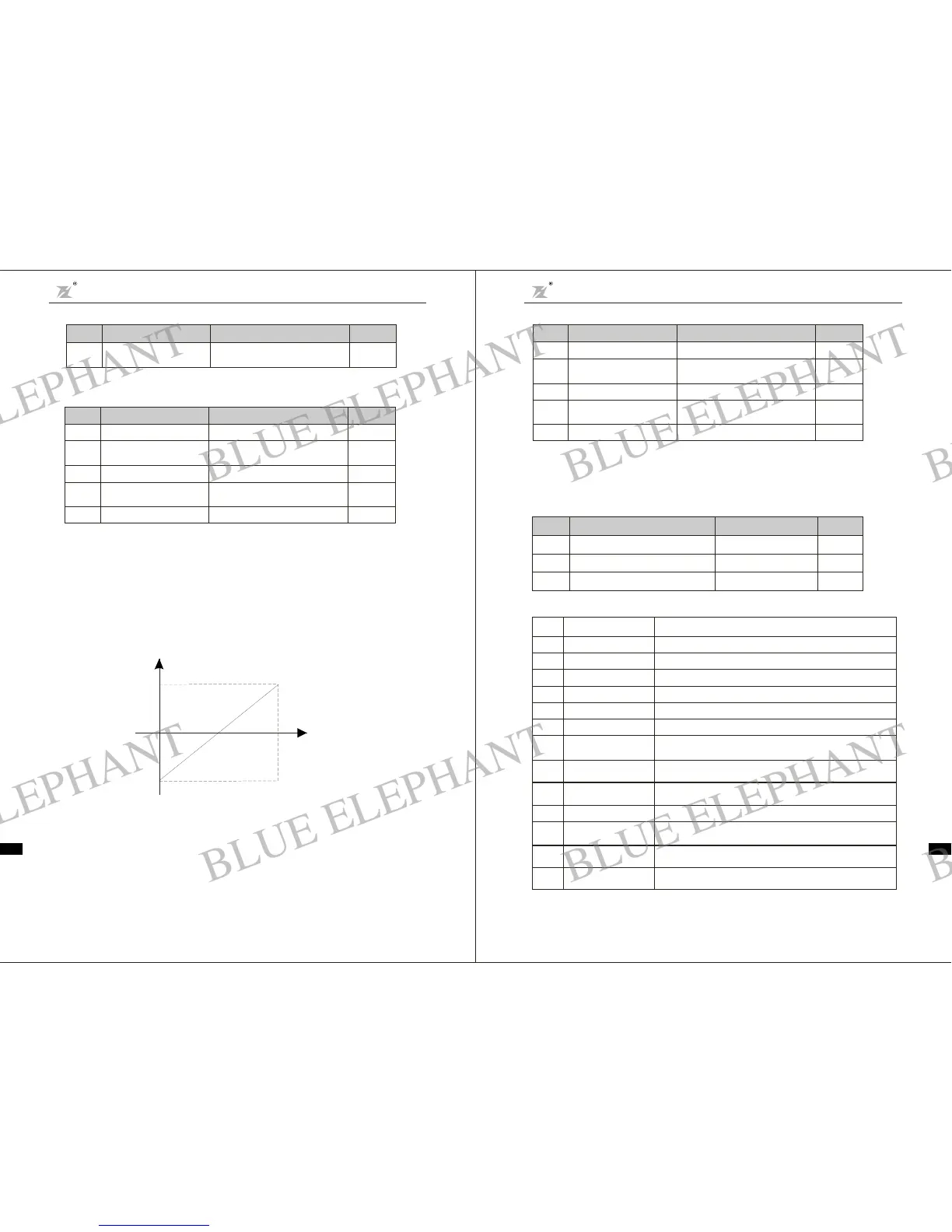
Above functioncodes define t he relationshipbetween an alog i nput voltage and the settingvalue that
analog input is corresponding to. When the analog input vol tage exceedsthe ra ngeof t he set maximumor
minimum input, thebeyond portionshould be c alculated w ithmaximuminput or minimumi nput.
When analo g input is amperage input, 0mA-20mA is corresponding to 0V-10V.
For differentapplications, t he correspondingnom inal value of analog setting 100.0% is different. For
de tai l s, p le as e refer to e ach applic ation des c r ipti on.
Following figuresshows several se ttings.N ote: low er limit must be less or equal to upper limit.VI VI
10V
0V
(20mA)
CI
()
0mA
100.0%
-10 0. 0%
frequency setting ,tor que ,PID setting,PIDfeedback
C ORRESPONDING SETTING
Fig. 6-12Relations hip between analog inputand s etti ngvalue
VI in put filteringtimedetermines analog input s ensitiveness .Increasingt his pa rameter,in order to
preventmalfunction causedby interfe rence to thea nalog, canstrengthenthe a nti-interference ability,
but re duce t he analog inp ut sensi tiven ess.
Open collector outputfunctions are indicatedas foll owingt able:
Function
Code
Nam e
Setting Range
Default
Value
F2.19
1
F2.20
F2. 21 3
0~1 0
0~1 0
Mo1out put sel ec tion
Relay output s electio n
Setting
Value
0
1
2
3
4
5
6
7
8
910~
Description
Function
Lower limit frequency
reaches
Upper limit frequency
reaches
Null speed operation
Zero Output
Inverter is running forward
Inverter is running reve rse
Fau lt output
FDT reaches
Reserved
Frequency reaches
When the operating fre quency reaches the lower frequency limit,
output ON signal.
When th e operating frequency reaches the upper frequency limit,
output ON signal.
When the inverter output frequency is less than the starting
frequency, output ON signal
Output t erminal has no function
ON signa l Ind icates the inverter is running for ward with output frequenc y.
ON signal Indicates the inverter is running reverse with output frequency.
Once inverter fault happens, output ON signal
please refer tothe detail description of function code F4.13,F4.14
please refer tothe detail description of function code F4.15
Reserved
Chapter 6 Param eterDescri ption
DZB Series
Chapter 6 Parameter Des cr ip ti on
DZB Series
CIfunctio nsettingsare sim ila r to V I settingmethod.
DZBSeriesinverterprovides2pathsofanaloginputport.
DZB Series i nverter standard unit has two mult ifunction digital output terminal,one (ortwo)
mult if uncti on relay ou tputterminals and oneanalog outputterminal.
F2.17
CI upper limi t
cor resp onding s ett ing
-100.0% 100 .0%
~
10 0.0%
F2.18
CI input filtering tim e
0. 0s 10.0 s
~
0.1s
F2.14
CI lower limit
0.0V 10.0 V
~
0.0V
F2.15
CI lower limit
cor re sponding s et ting
-100.0% 100.0%
~
0.0%
F2.16
CIu pper li mi t
0.0V 10.0 V
~
10.0V
Funct ion
Cod e
Name
Setting Range
Default
Value
F2.0 9
VI lowe r lim it
0.0V 10.0V
~
0.0V
F2. 1 0
VI lowe r lim it
corres pondi ng setting
-100.0% 100.0%
~
0.0%
F2 .11
VI upperlimit
0.0V 10.0V
~
10.0V
F2.1 2
VI upperlimit
corres pondi ng setting
-100.0% 100.0%
~
100.0%
F2.13
VI input filteri ng tim e
0.0s 10.0s
~
0.1 s
Function
Code
Name
Setting Ra nge
Default
Value
Ter minal UP/DOWN regulatesthe change rate offrequenc ysetting.
F2.08
UP/DOWNfrequency
incr emen t variabl e r ate
0.0 1 99.99Hz/s
~
0.50Hz/s
Function
Code
Name
Setting Range
Default
Value
11
12
13
high pressure reaches
detection(NC)
Pressure reaches at the F7.12 high pressure setting,NO output indication.
low pressure reaches
detection(NC)
high pressure reaches
detection(NO)
Pressure reaches at the F7.12 low pressure setting,NC output indication.
Pressure reaches at the F7.13 high pressure setting,NC output indication.
Reserved
-49- -50-
BLUE ELEPHANT
BLUE ELEPHANT
BLUE ELEPHANT
BLUE ELEPHANT
BLUE ELEPHANT
BLUE ELEPHANT
BLUE ELEPHANT
BLUE ELEPHANT
BLUE ELEPHANT
BLUE ELEPHANT
BLUE ELEPHANT
BLUE ELEPHANT
BLUE ELEPHANT
BLUE ELEPHANT
BLUE ELEPHANT
BLUE ELEPHANT
BLUE ELEPHANT
BLUE ELEPHANT
BLUE ELEPHANT
BLUE ELEPHANT
BLUE ELEPHANT
BLUE ELEPHANT
BLUE ELEPHANT
BLUE ELEPHANT
 Loading...