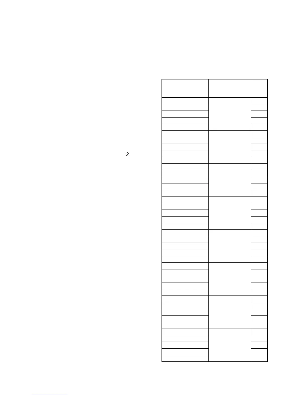
6-1 A7340EA
ELECTRICAL ADJUSTMENT INSTRUCTIONS
General Note:
“CBA” is abbreviation for “Circuit Board Assem-
bly.”
NOTE:
Electrical adjustments are required after replacing
circuit components and certain mechanical parts. It is
important to perform these adjustments only after all
repairs and replacements have been completed.
Also, do not attempt these adjustments unless the
proper equipment is available.
Test Equipment Required
1. DC Voltmeter
2. Pattern Generator
3. Color Analyzer
How to Set up the Service mode:
1. Turn the power on. (Use main power on the TV
unit.)
2. Press [STANDBY-ON], [2], [7], [1], and [ ] buttons
on the remote control unit in that order within 5
seconds.
- To cancel the service mode, press [STANDBY-ON]
button on the remote control.
1. Initial Setting
General
Enter the Service mode.
Set the each initial data as shown on table 1 below.
Table 1: Initial Data
ITEM
BUTTON
(on the remote
control)
DATA
VALUE
RF-BRT(PAL)
[SETUP(PAL)] →
[1]
130
RF-CNT(PAL) 170
RF-CLR-R(PAL) 84
RF-CLR-B(PAL) 81
RF-SHR(PAL) 143
AV-BRT(PAL)
[SETUP(PAL)] →
[2]
130
AV-CNT(PAL) 170
AV-CLR-R(PAL) 84
AV-CLR-B(PAL) 81
AV-SHR(PAL) 143
S-BRT(PAL)
[SETUP(PAL)] →
[3]
127
S-CNT(PAL) 175
S-CLR-R(PAL) 81
S-CLR-B(PAL) 86
S-SHR(PAL) 143
C-BRT(PAL)
[SETUP(PAL)] →
[4]
135
C-CNT(PAL) 190
C-CLR-R(PAL) 125
C-CLR-B(PAL) 140
C-SHR(PAL) 143
RF-BRT(SECAM)
[SETUP(SECAM)]
→ [1]
130
RF-CNT(SECAM) 180
RF-CLR-R(SECAM) 80
RF-CLR-B(SECAM) 80
RF-SHR(SECAM) 143
AV-BRT(SECAM)
[SETUP(SECAM)]
→ [2]
125
AV-CNT(SECAM) 180
AV-CLR-R(SECAM) 80
AV-CLR-B(SECAM) 80
AV-SHR(SECAM) 143
S-BRT(SECAM)
[SETUP(SECAM)]
→ [3]
125
S-CNT(SECAM) 180
S-CLR-R(SECAM) 80
S-CLR-B(SECAM) 80
S-SHR(SECAM) 143
C-BRT(SECAM)
[SETUP(SECAM)]
→ [4]
135
C-CNT(SECAM) 190
C-CLR-R(SECAM) 125
C-CLR-B(SECAM) 140
C-SHR(SECAM) 143