6-3 A7340EA
The following adjustment normally are not
attempted in the field. Only when replacing the
LCD Panel then adjust as a preparation.
3. White Balance Adjustment
Purpose: To mix red, green and blue beams correctly
for pure white.
Symptom of Misadjustment: White becomes bluish
or reddish.
1. Operate the unit for more than 20 minutes.
2. Input the White Purity.
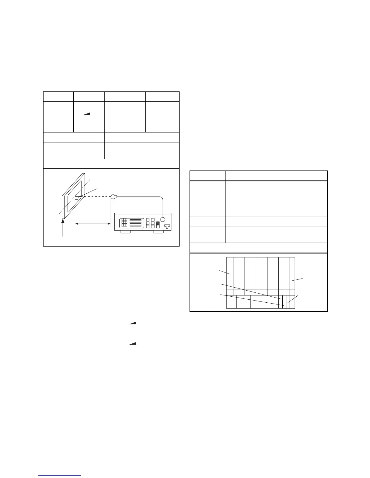
3. Set the color analyzer to the CHROMA mode and
bring the optical receptor to the center on the
LCD-Panel surface after zero point calibration as
shown above.
Note: The optical receptor must be set
perpendicularly to the LCD Panel surface.
4. [RF/AV2(CVBS)]
Enter the Service mode. Press [ -] button on the
remote control unit and select “C/D/S-1” mode.
[AV1(RGB)]
Enter the Service mode. Press [ -] button on the
remote control unit and select “C/D/S-2” mode.
5. [RF/AV2(CVBS)]----(APL 80%)
Press [6] button to select “DB(C/D/S-1)” for Blue
adjustment. Press [4] button to select “DR(C/D/S-
1)” for Red adjustment. When “x” value and “y”
value are not within specification, adjust “DB (C/D/
S-1)” or “DR (C/D/S-1)”. Refer to “1. Initial Setting.”
[RF/AV2(CVBS)]----(APL 20%)
Press [3] button to select “COB(C/D/S-1)” for Blue
adjustment. Press [1] button to select “COR(C/D/
S-1)” for Red adjustment. When “x” value and “y”
value are not within specification, adjust “COB (C/
D/S-1)” or “COR (C/D/S-1)”. Refer to “1. Initial
Setting.”
6. [AV1(RGB)]----(APL 80%)
Press [6] button to select “C-DB(C/D/S-2)” for Blue
adjustment. Press [4] button to select “C-DR(C/D/
S-2)” for Red adjustment.When “x” value and “y”
value are not within specification, adjust “C-DB(C/
D/S-2)” or “C-DR(C/D/S-2)”. Refer to “1. Initial
Setting.”
[AV1(RGB)]----(APL 20%)
Press [3] button to select “C-COB(C/D/S-2)” for
Blue adjustment. Press [1] button to select “C-
COR(C/D/S-2)” for Red adjustment.When “x”
value and “y” value are not within specification,
a d j u s t “ C - C O B ( C / D / S - 2 ) ” o r “ C - C O R ( C / D / S - 2 ) ” .
Refer to “1. Initial Setting.”
7. Turn the power off and on again.
4. Sub-Brightness Adjustment
Purpose: To get proper brightness.
Symptom of Misadjustment: If Sub-Brightness is
incorrect, proper brightness cannot be obtained by
adjusting the Brightness Control.
1. Enter the Service mode. Then input above signal.
2. [RF/AV2(CVBS)]
Press [SETUP] button on the remote control unit
and press [1] on the service remote control
(selecting “BRT” mode).
[AV1(RGB)]
Press [SETUP] button on the service remote
control unit and press [3] on the service remote
control (selecting “C-BRT” mode).
3. Make sure that contrast and brightness controls
are set to initial position.
4. Confirm “C” position was beginning to bright.
5. If “C” position was beginning to bright, no need to
adjust.
6. If “C” position is not available or to be highly
brightness, then adjust IIC-BUS dada.
[RF/AV2(CVBS)]: BRT
[AV1(RGB)]: C-BRT
7. Turn the power off and on again.
Test Point Adj. Point Mode Input
Screen
[ -]
button
[RF/AV2(CVBS)]
C/D/S-1
[AV1(RGB)]
C/D/S-2
White Purity
(APL 80%)
or
(APL 20%)
M. EQ. Spec.
Pattern Generator,
Color analyzer
x=
0.276 ± 0.03
,
y=
0.282 ± 0.03
Figure
Color Analyzer
It carries out in a darkroom.
L = 3 cm
Perpendicularity
INPUT: WHITE 80%
Adj. Point Input
[SETUP]
button
Ant. input, Any channel,
SMPTE pattern,
[RF/AV2(CVBS)]
: CG-931 (KENWOOD),
[AV1(RGB)]: CG-931 (KENWOOD),
W/O SETUP 7.5IRE
M. EQ. Spec.
Pattern
Generator
See below
Figure
White
Black
C positionB position
A position