NAVNET QUICK SETUP GUIDE, multiple component configuration with 10.4" and 7" displays
(optional equipment shown)
cable
included & attached
to the BBWGPS
BBWGPS
000-125-237 cable
supplied with PG1000
or use a # 000-117-603
cable to connect to a
external heading device
Heading device (optional)
Furuno PG1000
OR
other external
(required for overlay)
AD10 Furuno format
required for ARP11
radar autoplotter option
(optional)
FURUNO
NavPilot 500
OR
other Autopilot
000-144-601 (0.5m)
Radar antenna
connection
(GP 1900C, N/A)
DATA 2
NETWORK
DATA 1
DATA 3
DATA 4
(see wiring page for more)
12-24 VDC
12-24 VDC
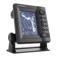
RADAR DISPLAY SETUP:
1. Confirm initial configuration using the single display setup page
2. Press [MENU], [SYSTEM CONFIGURATION], [SYSTEM SETUP], [PORT SETUP],
[OUTPUT THROUGH NETWORK], select and turn ON "GGA", "VTG" and "ZDA".
This sends required position, track, time and date information to all other network devices.
3. CHART SOURC
E: Press [EDIT] and add PLOTTER (under NETWORK SETUP menu)
1. Connect and configure a single display and network sounder (if installed) before continuing(see page 1).
2. Confirm no simulation modes are selected, [SIM] would display in upper left corner.
3. Connect all displays (any combination of up to four 7 inch and/or 10.4 inch displays total can be used in
the network) and any combination of other network devices such as a BBFF1, BBFF3, or FAX30.
4. Use a standard ethernet hub if three (3) or more network devices are present.
a) Care should be taken to supply a stable voltage to the hub from the primary display (any 7 pin port
with 12VDC output) or
other stable and filtered "12VDC" supply voltage.
"INSTALLATION MENU required for following. Press and hold [MENU] while powering on display"
5.
All disp
lays must have a different "HOST NAME" and "IP ADDRESS".
a) A two(2) display system will usually be correct. Three(3) or more displays will require configuration
c) Press [MENU], [SYSTEM CONFIGURATION], [INSTALLATION SETUP], "NETWORK SETUP" to configure.
b) Refer to the IP ADDRESS, HOST NAME chart for examples. DO NOT rename the "RADAR" display.
6. CHART SOURCE: Input all displays [HOST NAME] on network, omit own HOST NAME
(see below setup boxes and"General Information" page for detailed instructions)
MODEL IP ADDRESS alternate HOST NAME alternate
1722/1732/1742/1762 172.031.003.004 172.031.003.006 RADAR RADAR1
1722C/1732C/1742C/1762C 172.031.003.001 172.031.003.007 RADAR RADAR2
1833/1933/1943 172.031.003.002 172.031.003.008 RADAR RADAR3
1833C/1933C/1943C/1953C 172.031.003.003 172.031.003.009 RADAR RADAR4
GP-1700 172.031.014.002 172.031.014.010 PLOTTER PLOTTER1
GP-1700C 172.031.014.001 172.031.014.011 PLOTTER PLOTTER2
GP-1900C 172.031.003.005 172.031.003.012 PLOTTER PLOTTER3
BBFF1 172.031.092.001 Do not change SOUNDER Do not change
BBFF3 (use IP/host switch) 172.031.092.001 172.031.092.011- 019 SOUNDER SOUNDER1-9
FAX30 172.031.008.001 N/A WXFAX N/A
see BBFF3 page for
all configurations
and setup information
FAX30
12-24 VDC
000-144-463
POWER OFF then ON after any "MENU CHANGES" to store the new information.
Refer to the Installation and Operator Manuals regarding detailed information on any steps
DATA 3 (same as DATA 4 on 10.4")
RADAR
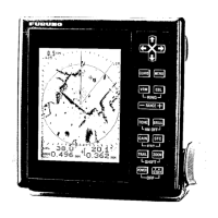
PLOTTER
GENERAL CONFIGURATION:
000-146-289
(5m), null cable
supplied w/BBFF3
BBFF1 SOUNDER
12-24 VDC
BBFF3 SOUNDER1
12-24 VDC
(if installed)
refer to the BBFF3 and
FAX30 manuals for
additional information
Connect to hub uplink port only
000-144-463
(0.5m) adapter
000-144-423
(10m) cable
HUB
(local supply)
NETWORK
000-144-463
000-144-424
(20m) cable
000-144-425
(30m) cable
PLOTTER DISPLAY SETUP:
1. If BBFF1 is installed refer to "single display setup page" for
"Displaying digital temperature and depth on NavNet display(s)".
2. Set up general function and display parameters using the
"NavNet General Information" page and operators manual.
3. CHART SOURC
E: Press [EDIT] and add RADAR (under
NETWORK SETUP menu)
 Loading...