2. WIRING
2-2
Wiring considerations
• USB cable lengths should be within 5 m, with or without the USB extension cable. Full
function cannot be guaranteed if the overall length exceeds 5 m.
• The PCU-3010 is not compatible with the USB 3.0 equipment.
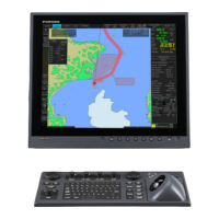
• USB cables should be secured using the clamp highlighted in the figure below.
• LAN cable lengths between units should be within 50 m.
• The Display Port outputs FULL HD resolution. To connect an analog input device, use
the DP-VGA adapter (supplied).
• If extension or division of the RGB cable is required, use the IMAGENICS type CIF-
12H RGB divider.
• Ensure all grounding wires are connected between grounding terminals on each
equipment and ship’s earth.
• If a UPS (user supply) is connected to this equipment, ensure the grounding lamp
does not light up.
• Use the following LAN cables for the network if they are available locally.
• Sensor Network: Cat5 or better.
• Gateway Network: Cat5e or better.
• If LAN cables are not available locally, use the optional LAN cables as below:
• Sensor network - FR-FTPC-CY (Cat5 equivalent).
• Gateway network - DTI-C5E350 VCV (Cat5e equivalent).
• ECDIS control unit RCU-024 and RCU-026 are not compatible with this equipment.
• To connect this equipment to a VR-3000/S, use the Display Port, with DP-VGA adapt-
er (supplied). The Display Port outputs FULL HD resolution and requires a synchro-
nizer to convert the output to UXGA.
• When connecting a digital input device, use our recommended DP-DVI adapter (man-
ufacturer: Hatteland Technology, model: DPM2DVI-DF-A1 (SG300000198)).
• When connecting a VDR device via LAN, connect the VDR device to the LAN2 port.
Cable clamp for USB cables

 Loading...