7.2 Antenna Unit
7-6
2. Control between RFC board and MD board
The RFC board outputs four TX triggers to the MD board to generate TX pulses
corresponding to pulse length set in the Processor unit. Changing the timing of each
trigger and pulse length controls the TX pulse length and waveform. The TX pulses are
S1, S2, M1, M2, M3 and L. When voltage higher than the specified TX high voltage
(TX-HV) is applied onto the MD board, the RFC board stops TX triggers.
3. Control between RFC board and IF board
The RFC board controls the IF board based on the control information from the SPU
board. This includes the control bandwidth, STC waveform output according to
GAIN/STC information, MBS, and the cable correction. The IF board outputs STC
DETECT signals to the RFC board to create an AUTO STC curve, which are converted
into serial data and sent to the SPU board.
4. Monitor of TR unit
The RFC board detects TUNE IND voltage, Magnetron current, DI-Monitor voltage,
and each supply voltage from the circuits. Detected signals are converted into serial data
and sent to the SPU board. By executing [Menu] -> 9 -> 8 -> 2:Self Test, values
detected in the TR unit can be monitored. See page.6-6 for details.
5. HD and B.P
HD and B.P signals are sent from the B.P GEN board to the RFC board. B.P is
outputted at 265 pulses/rev on the S-band radar and 360 pulses/rev on the X-band radar.
These signals are subjected to waveform shaping on the RFC board, converted into
serial data and sent to the SPU board.
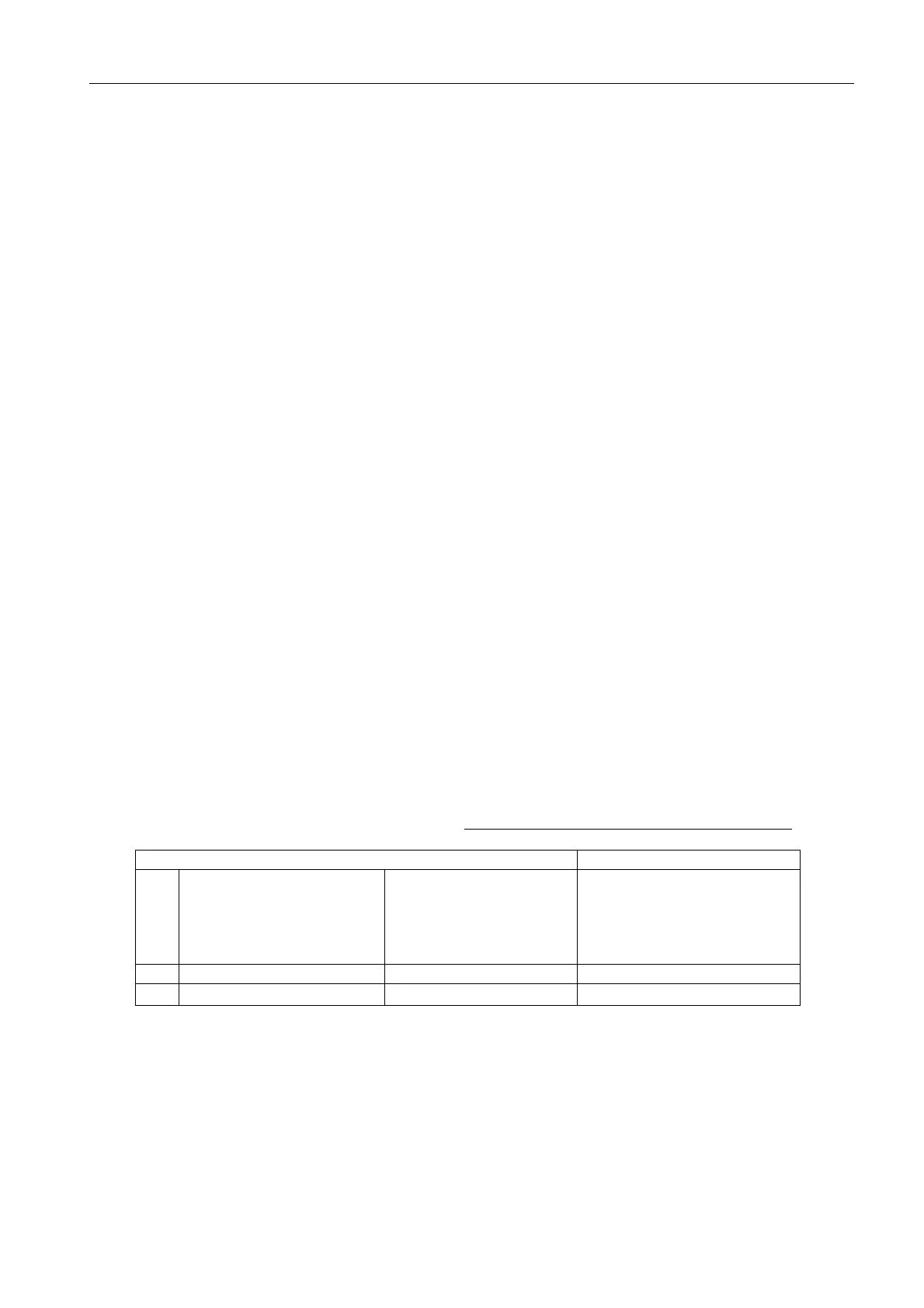
6. Memory used for RFC board
The table below shows major applications of the memory of the RFC board.
Table 7.2.1 Memory used for RFC board
Memory Application
U26 XC18V01S020I
ISP PROM
(In System Programming)
The circuit of U17 (FPGA) is
written on it. When the power
is turned on, the program is
sent to the FPGA to start the
FPGA.
U28 MBM29LV800BA 90 PFTN 8 M Flash-ROM RFC CPU program
U27
μPD441000LGU B85A
1 M SRAM: RFC CPU work memory

 Loading...