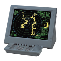
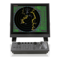
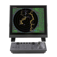
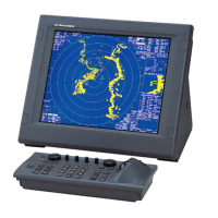
1.2 Configuration
1-11
1.2.4 Antenna unit
1. Applicable model: FAR-2117, 2127, 2817, 2827, 2117-BB and 2127-BB
Table 1.2.2 Configuration of 12 kW and 25 kW X-band Radar
Transceiver Gear box Radiator
Model
Type Output Type
Motor
(24 VDC)
rpm PM
De-
icer
Type
(Length)
RSB-096 D8G-516 24
FAR-2117
FAR-2117-BB
FAR-2817
RTR-078 12 kW
RSB-097 D8G-571 42
RSB-096 D8G-516 24
FAR-2127
FAR-2127-BB
FAR-2827
RTR-079 25 kW
RSB-097 D8G-571 42
Yes
XN-12AF
(4 ft)
XN-20AF
(6.5 ft)
XN-24AF
(8 ft)
FAR-2127-5A
FAR-2827-5A
RTR-079 25 kW RSB-109 D8G-516 24
PM-31
No
XN-5A
(10 ft)
The optional De-icer must be incorporated in the factory. (not a field job)
The De-icer power is 100 VAC, 1
, 50/60 Hz. When the De-icer power is except for 100
VAC, a transformer unit (RU-3305) is used.
When mounting a performance monitor (PM-31), change the Gearbox cover with the
PM-31. The antenna revolution speed depends on the type of the Gearbox and the PWR
board of the Processor unit.
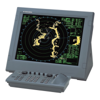
Fig. 1.2.6 Configuration of 12 kW and 25 kW X-band Radars
FURUNO
RW-9600
Scanner
RPU-013
100VAC 1 50/60Hz
100/110/200/220VAC
1 50/60Hz
RU-3305
For De-Icer
(Transformer)
DPYCY-1.5
PM-31
RU-3305

 Loading...
